×
ToyotaParts- Hello
- Login or Register
- Quick Links
- Live Chat
- Track Order
- Parts Availability
- RMA
- Help Center
- Contact Us
- Shop for
- Toyota Parts
- Scion Parts
My Garage
My Account
Cart
OEM 2005 Toyota Highlander Sway Bar Kit
Stabilizer Sway Bar Set- Select Vehicle by Model
- Select Vehicle by VIN
Select Vehicle by Model
orMake
Model
Year
Select Vehicle by VIN
For the most accurate results, select vehicle by your VIN (Vehicle Identification Number).
3 Sway Bar Kits found

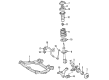
2005 Toyota Highlander Bar, Stabilizer
Part Number: 48811-0E020$279.01 MSRP: $398.36You Save: $119.35 (30%)Ships in 1-3 Business DaysProduct Specifications- Other Name: Sway Bar
- Replaces: 48811-0E010
- Item Weight: 8.10 Pounds
- Item Dimensions: 46.4 x 12.4 x 5.1 inches
- Condition: New
- SKU: 48811-0E020
- Warranty: This genuine part is guaranteed by Toyota's factory warranty.

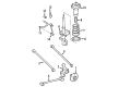
2005 Toyota Highlander Stabilizer Bar, Rear
Part Number: 48805-48110$222.74 MSRP: $318.02You Save: $95.28 (30%)Ships in 1-3 Business DaysProduct Specifications- Other Name: Bar Sub-Assembly, Rear Stabilizer; Suspension Stabilizer Bar, Rear; Sway Bar; Bar, Stabilizer, Rear
- Position: Rear
- Part Name Code: 48812
- Item Weight: 5.20 Pounds
- Item Dimensions: 41.1 x 9.4 x 3.4 inches
- Condition: New
- Fitment Type: Direct Replacement
- SKU: 48805-48110
- Warranty: This genuine part is guaranteed by Toyota's factory warranty.
 Product Specifications
- Other Name: Bar, Stabilizer, Rear; Suspension Stabilizer Bar, Rear; Sway Bar
- Position: Rear
- Part Name Code: 48812
- Item Weight: 5.30 Pounds
- Item Dimensions: 41.6 x 9.3 x 3.4 inches
- Condition: New
- Fitment Type: Direct Replacement
- SKU: 48812-48140
- Warranty: This genuine part is guaranteed by Toyota's factory warranty.
2005 Toyota Highlander Sway Bar Kit
Looking for affordable OEM 2005 Toyota Highlander Sway Bar Kit? Explore our comprehensive catalogue of genuine 2005 Toyota Highlander Sway Bar Kit. All our parts are covered by the manufacturer's warranty. Plus, our straightforward return policy and speedy delivery service ensure an unparalleled shopping experience. We look forward to your visit!
2005 Toyota Highlander Sway Bar Kit Parts Q&A
- Q: How to replace the front Sway Bar Kit on 2005 Toyota Highlander?A: The front sway bar kit replacement process starts with taking off the front wheel after uninstalling the front sway bar link assembly LH through removal of its 2 nuts yet holding the ball joint in place with a 6mm hexagon wrench. The same method should be used to replace the front sway bar link assembly RH. The front sway bar link assembly LH must be checked with the ball joint stud moved back and forth 5 times before nut installation followed by torque wrench measurement at 0.05 - 1.96 Nm (0.5 - 20 kgf-cm; 0.4 - 17.4 inch lbs.) during the 5th turn. Start with removing the 2 bolts from the front sway bar bracket No.1 LH then proceed with front sway bar bracket No.1 RH. After removing the front sway bar bracket No.2 LH from its sway bar bush proceed with the same operation on front sway bar bracket No.2 RH. First disconnect the tie rod end sub-assembly LH through the use of Special Service Tool: 09628-62011 and follow the same procedure for disconnecting the tie rod end sub-assembly RH. Split the steering intermediate shaft chain assembly before using Special Service Tools: 09023-12701 to detach the steering outlet return tube and removing the pressure feed tube assembly. First remove the power steering link assembly and secondly remove the front sway bar bush (No.1) by removing its two sway bar kit-positioned bushes then remove the sway bar kit front from the vehicle. You should first install the sway bar kit front into the vehicle then add the front sway bar bush No.1 into position with its bush stopper on the front side of the bar. The technician will reinstall the power steering link assembly as well as the pressure feed tube assembly with Special Service Tool: 09023-12701 and the steering gear outlet return tube. The installation of the tie rod end sub-assembly LH and RH follows the same procedure for both sides after connecting the steering intermediate shaft sub-assembly. The front sway bar bracket No.2 LH should be installed on the sway bar bush No.1 before the same steps are done for front sway bar bracket No.2 RH. Connect the front sway bar bracket No.1 LH through 2 bolts which need a torque setting of 16 Nm (163 kgf-cm, 12 ft. lbs.) followed by bracket No.1 RH using the same procedure. Apply 74 Nm (755 kgf-cm, 55 ft. lbs.) torque to install each of the front sway bar link's two nuts when doing the left-hand side procedure. When the ball joint turns with the nut, hold it using a hexagon wrench and perform the same operation on the right-hand side sway bar link. You must first install the front wheel by tightening it to 103 Nm (1,050 kgf-cm, 76 ft. lbs.) then perform power steering fluid bleeding followed by fluid leakage inspections of the power steering system and adjustments to the steering wheel center point and front wheel alignment.
Related 2005 Toyota Highlander Parts
 2005 Toyota Highlander Control Arm
 2005 Toyota Highlander Axle Shaft
 2005 Toyota Highlander Ball Joint
 2005 Toyota Highlander Bump Stop
 2005 Toyota Highlander Rear Crossmember
 2005 Toyota Highlander Shock Absorber
 2005 Toyota Highlander Shock and Strut Boot
 2005 Toyota Highlander Strut Housing
 2005 Toyota Highlander Suspension Strut Rod
 2005 Toyota Highlander Sway Bar Bracket
 2005 Toyota Highlander Sway Bar Link
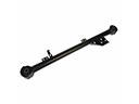 2005 Toyota Highlander Trailing Arm