×
ToyotaParts- Hello
- Login or Register
- Quick Links
- Live Chat
- Track Order
- Parts Availability
- RMA
- Help Center
- Contact Us
- Shop for
- Toyota Parts
- Scion Parts
My Garage
My Account
Cart
OEM 2006 Toyota Highlander Sway Bar Kit
Stabilizer Sway Bar Set- Select Vehicle by Model
- Select Vehicle by VIN
Select Vehicle by Model
orMake
Model
Year
Select Vehicle by VIN
For the most accurate results, select vehicle by your VIN (Vehicle Identification Number).
4 Sway Bar Kits found

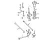
2006 Toyota Highlander Bar, Stabilizer
Part Number: 48811-0E020$279.01 MSRP: $398.36You Save: $119.35 (30%)Ships in 1-3 Business DaysProduct Specifications- Other Name: Sway Bar
- Replaces: 48811-0E010
- Item Weight: 8.10 Pounds
- Item Dimensions: 46.4 x 12.4 x 5.1 inches
- Condition: New
- SKU: 48811-0E020
- Warranty: This genuine part is guaranteed by Toyota's factory warranty.


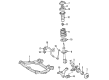
2006 Toyota Highlander Bar, Stabilizer, Front
Part Number: 48811-48060$136.88 MSRP: $193.76You Save: $56.88 (30%)Ships in 1-3 Business DaysProduct Specifications- Other Name: Sway Bar
- Position: Front
- Part Name Code: 48811
- Item Weight: 7.60 Pounds
- Item Dimensions: 45.1 x 12.4 x 5.1 inches
- Condition: New
- Fitment Type: Direct Replacement
- SKU: 48811-48060
- Warranty: This genuine part is guaranteed by Toyota's factory warranty.

2006 Toyota Highlander Stabilizer Bar, Rear
Part Number: 48805-48110$222.74 MSRP: $318.02You Save: $95.28 (30%)Ships in 1-3 Business DaysProduct Specifications- Other Name: Bar Sub-Assembly, Rear Stabilizer; Suspension Stabilizer Bar, Rear; Sway Bar; Bar, Stabilizer, Rear
- Position: Rear
- Part Name Code: 48812
- Item Weight: 5.20 Pounds
- Item Dimensions: 41.1 x 9.4 x 3.4 inches
- Condition: New
- Fitment Type: Direct Replacement
- SKU: 48805-48110
- Warranty: This genuine part is guaranteed by Toyota's factory warranty.
 Product Specifications
- Other Name: Bar, Stabilizer, Rear; Suspension Stabilizer Bar, Rear; Sway Bar
- Position: Rear
- Part Name Code: 48812
- Item Weight: 5.30 Pounds
- Item Dimensions: 41.6 x 9.3 x 3.4 inches
- Condition: New
- Fitment Type: Direct Replacement
- SKU: 48812-48140
- Warranty: This genuine part is guaranteed by Toyota's factory warranty.
2006 Toyota Highlander Sway Bar Kit
Looking for affordable OEM 2006 Toyota Highlander Sway Bar Kit? Explore our comprehensive catalogue of genuine 2006 Toyota Highlander Sway Bar Kit. All our parts are covered by the manufacturer's warranty. Plus, our straightforward return policy and speedy delivery service ensure an unparalleled shopping experience. We look forward to your visit!
2006 Toyota Highlander Sway Bar Kit Parts Q&A
- Q: How to service and repair the front Sway Bar Kit on 2006 Toyota Highlander?A: Service and repair of the front sway bar kit starts with front wheel removal then front sway bar link assembly LH disassembly by untightening the 2 nuts after applying a hexagon wrench (6 mm) to retain the stud. The same service procedure should be followed for the RH side. The next service step requires the front sway bar bracket No. 1 LH to be unbolted through unscrewing its two bolts before following the same process on the RH side. The next step involves taking off the front sway bar bracket No. 2 LH from the sway bar bush before proceeding with the removal of the RH side using the same approach. Special Service Tool: 09628-62011 allows users to disconnect the tie rod end sub-assembly LH before proceeding to do the same with the RH side. The procedure starts with separating the steering intermediate shaft subassembly before using Special Service Tool: 09023-12701 to remove the steering gear outlet return tube. Finally the procedure ends with disconnecting the pressure feed tube assembly. The work requires removal of power steering link assembly and front sway bar bush No. 1 by extracting 2 bushes from the sway bar kit before removing the sway bar kit front from the vehicle. The inspection process of the LH front sway bar link assembly requires BALL joint stud movement five times followed by torque measurement of turning torque between 0.05 to 1.96 Nm (0.5 to 20 kgf-cm, 0.4 to 17.4 inch lbs.); failure to meet specification requires assembly replacement. Begin by attaching the sway bar kit front to the vehicle followed by installing front sway bar bush No. 1 which should face the rear direction with its cutout on the outer edge of the bush stopper. Proceed by mounting the power steering link assembly followed by the pressure feed tube assembly using Special Service Tool: 09023-12701 before attaching the steering gear outlet return tube. Connect the steering intermediate shaft subassembly and then proceed to install both tie rod end sub-assemblies LH and RH while maintaining equal procedures. Set up the front sway bar bracket No. 2 LH at the sway bar bush No. 1 and duplicate this installation on the RH side. Install and tighten two bolts only on front sway bar bracket No. 1 LH while applying 16 Nm (163 kgf-cm, 12 ft. lbs.) torque and repeat the same process for the right-hand side. Fits the front sway bar link assembly LH with 2 nuts while applying 74 Nm (755 kgf-cm, 55 ft. lbs. of torque); in case the ball joint moves with the nut keep it steady by using a hexagon wrench before repeating the installation process for the RH side. Reinstallation of the front wheel should be followed by power steering fluid bleeding as well as leak testing and centering the steering wheel and checking front wheel alignment.
Related 2006 Toyota Highlander Parts
 2006 Toyota Highlander Control Arm
 2006 Toyota Highlander Axle Shaft
 2006 Toyota Highlander Ball Joint
 2006 Toyota Highlander Bump Stop
 2006 Toyota Highlander Rear Crossmember
 2006 Toyota Highlander Shock Absorber
 2006 Toyota Highlander Shock and Strut Boot
 2006 Toyota Highlander Strut Housing
 2006 Toyota Highlander Suspension Strut Rod
 2006 Toyota Highlander Sway Bar Bracket
 2006 Toyota Highlander Sway Bar Link
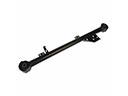 2006 Toyota Highlander Trailing Arm