×
ToyotaParts- Hello
- Login or Register
- Quick Links
- Live Chat
- Track Order
- Parts Availability
- RMA
- Help Center
- Contact Us
- Shop for
- Toyota Parts
- Scion Parts
My Garage
My Account
Cart
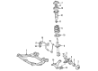
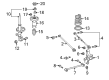
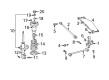
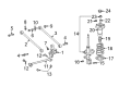
OEM 2006 Toyota Highlander Shock Absorber
Suspension Shock Absorber- Select Vehicle by Model
- Select Vehicle by VIN
Select Vehicle by Model
orMake
Model
Year
Select Vehicle by VIN
For the most accurate results, select vehicle by your VIN (Vehicle Identification Number).
12 Shock Absorbers found


2006 Toyota Highlander Absorber Assembly, Shock
Part Number: 48520-A9220$217.49 MSRP: $310.53You Save: $93.04 (30%)Ships in 1-3 Business DaysProduct Specifications- Other Name: ABSORBER ASSY, SHOCK; Suspension Strut Assembly Kit; Shock Absorber
- Position: Driver Side
- Replaces: 48520-49555
- Item Weight: 15.70 Pounds
- Item Dimensions: 28.5 x 8.6 x 8.0 inches
- Condition: New
- SKU: 48520-A9220
- Warranty: This genuine part is guaranteed by Toyota's factory warranty.

2006 Toyota Highlander Strut Assembly, Passenger Side
Part Number: 48510-A9360$189.07 MSRP: $269.94You Save: $80.87 (30%)Ships in 1-3 Business DaysProduct Specifications- Other Name: Absorber Set, Shock; Suspension Strut Assembly Kit; Complete Strut Kit; Complete Strut; Shock Absorber; Strut
- Position: Passenger Side
- Replaces: 48510-49445
- Item Weight: 15.70 Pounds
- Item Dimensions: 26.9 x 8.9 x 7.6 inches
- Condition: New
- SKU: 48510-A9360
- Warranty: This genuine part is guaranteed by Toyota's factory warranty.


2006 Toyota Highlander Strut, Rear Passenger Side
Part Number: 48530-49615$172.71 MSRP: $244.50You Save: $71.79 (30%)Ships in 1-3 Business DaysProduct Specifications- Other Name: Absorber Assembly, Shock; Rear Right Suspension Strut; Complete Strut Kit; Shock Absorber; Absorber Assembly, Shock, Rear Passenger Side
- Manufacturer Note: MARK 48530-48290
- Position: Rear Passenger Side
- Part Name Code: 48530
- Item Weight: 6.50 Pounds
- Item Dimensions: 25.8 x 6.8 x 5.7 inches
- Condition: New
- Fitment Type: Direct Replacement
- SKU: 48530-49615
- Warranty: This genuine part is guaranteed by Toyota's factory warranty.


2006 Toyota Highlander Strut, Rear Driver Side
Part Number: 48540-49245$162.84 MSRP: $230.53You Save: $67.69 (30%)Ships in 1-3 Business DaysProduct Specifications- Other Name: Absorber Assembly, Shock; Rear Left Suspension Strut; Complete Strut Kit; Shock Absorber; Absorber Assembly, Shock, Rear Driver Side
- Manufacturer Note: MARK 48540-48210
- Position: Rear Driver Side
- Part Name Code: 48540
- Item Weight: 14.20 Pounds
- Item Dimensions: 26.6 x 6.8 x 5.7 inches
- Condition: New
- Fitment Type: Direct Replacement
- SKU: 48540-49245
- Warranty: This genuine part is guaranteed by Toyota's factory warranty.

2006 Toyota Highlander Strut, Rear Passenger Side
Part Number: 48530-49415$162.84 MSRP: $230.53You Save: $67.69 (30%)Ships in 1-3 Business DaysProduct Specifications- Other Name: Absorber Assembly, Shock; Rear Right Suspension Strut; Complete Strut Kit; Shock Absorber; Absorber Assembly, Shock, Rear Passenger Side
- Manufacturer Note: MARK 48530-48200
- Position: Rear Passenger Side
- Part Name Code: 48530
- Item Weight: 13.30 Pounds
- Item Dimensions: 25.8 x 6.5 x 5.7 inches
- Condition: New
- Fitment Type: Direct Replacement
- SKU: 48530-49415
- Warranty: This genuine part is guaranteed by Toyota's factory warranty.


2006 Toyota Highlander Strut, Rear Passenger Side
Part Number: 48530-49555$160.61 MSRP: $227.36You Save: $66.75 (30%)Ships in 1-3 Business DaysProduct Specifications- Other Name: Absorber Assembly, Front Right-Hand; Rear Right Suspension Strut; Strut Assembly Kit; Shock Absorber; Absorber Assembly, Shock, Rear Passenger Side
- Manufacturer Note: MARK 48530-48230
- Position: Rear Passenger Side
- Part Name Code: 48530
- Item Weight: 12.30 Pounds
- Item Dimensions: 26.1 x 6.8 x 5.8 inches
- Condition: New
- Fitment Type: Direct Replacement
- SKU: 48530-49555
- Warranty: This genuine part is guaranteed by Toyota's factory warranty.


2006 Toyota Highlander Strut, Rear Driver Side
Part Number: 48540-49295$156.15 MSRP: $221.04You Save: $64.89 (30%)Ships in 1-3 Business DaysProduct Specifications- Other Name: Absorber Assembly, Front Left-Hand; Rear Left Suspension Strut; Strut Assembly Kit; Shock Absorber; Absorber Assembly, Shock, Rear Driver Side
- Manufacturer Note: MARK 48540-48230
- Position: Rear Driver Side
- Part Name Code: 48540
- Item Weight: 12.80 Pounds
- Item Dimensions: 25.6 x 6.8 x 5.9 inches
- Condition: New
- Fitment Type: Direct Replacement
- SKU: 48540-49295
- Warranty: This genuine part is guaranteed by Toyota's factory warranty.
2006 Toyota Highlander Strut
Part Number: 48530-49335$230.77 MSRP: $329.49You Save: $98.72 (30%)Ships in 1-3 Business DaysProduct Specifications- Other Name: Absorber Assembly, Shock; Shock Absorber
- Replaces: 48530-49435
- Item Weight: 12.40 Pounds
- Condition: New
- SKU: 48530-49335
- Warranty: This genuine part is guaranteed by Toyota's factory warranty.
2006 Toyota Highlander Strut
Part Number: 48540-49225$222.74 MSRP: $318.02You Save: $95.28 (30%)Ships in 1-3 Business DaysProduct Specifications- Other Name: Absorber Assembly, Shock; Shock Absorber
- Replaces: 48540-49265
- Item Weight: 13.50 Pounds
- Condition: New
- SKU: 48540-49225
- Warranty: This genuine part is guaranteed by Toyota's factory warranty.

2006 Toyota Highlander Strut, Rear Driver Side
Part Number: 48540-49325$187.32 MSRP: $267.45You Save: $80.13 (30%)Ships in 1-3 Business DaysProduct Specifications- Other Name: Absorber Assembly, Shock; Suspension Strut, Rear Left; Shock Absorber
- Position: Rear Driver Side
- Replaces: 48540-49365
- Item Weight: 12.70 Pounds
- Condition: New
- SKU: 48540-49325
- Warranty: This genuine part is guaranteed by Toyota's factory warranty.
2006 Toyota Highlander Strut, Rear Passenger Side
Part Number: 48530-49595$185.11 MSRP: $264.29You Save: $79.18 (30%)Ships in 1-3 Business DaysProduct Specifications- Other Name: Absorber Assembly, Shock; Suspension Strut, Rear Right; Shock Absorber
- Position: Rear Passenger Side
- Replaces: 48530-49625
- Item Weight: 12.60 Pounds
- Condition: New
- SKU: 48530-49595
- Warranty: This genuine part is guaranteed by Toyota's factory warranty.
2006 Toyota Highlander Strut, Rear Driver Side
Part Number: 48540-49355$172.71 MSRP: $244.50You Save: $71.79 (30%)Ships in 1-3 Business DaysProduct Specifications- Other Name: Absorber Assembly, Shock; Rear Left Suspension Strut; Complete Strut Kit; Shock Absorber; Absorber Assembly, Shock, Rear Driver Side
- Manufacturer Note: MARK 48540-48290
- Position: Rear Driver Side
- Part Name Code: 48540
- Item Weight: 6.80 Pounds
- Item Dimensions: 26.6 x 6.6 x 5.9 inches
- Condition: New
- Fitment Type: Direct Replacement
- SKU: 48540-49355
- Warranty: This genuine part is guaranteed by Toyota's factory warranty.
2006 Toyota Highlander Shock Absorber
Looking for affordable OEM 2006 Toyota Highlander Shock Absorber? Explore our comprehensive catalogue of genuine 2006 Toyota Highlander Shock Absorber. All our parts are covered by the manufacturer's warranty. Plus, our straightforward return policy and speedy delivery service ensure an unparalleled shopping experience. We look forward to your visit!
2006 Toyota Highlander Shock Absorber Parts Q&A
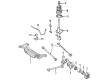
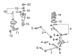
- Q: How to effectively service and repair a shock absorber on 2006 Toyota Highlander?A: Service and repair procedures for the front strut assembly start with front wheel removal and after that separate the front stabilizer link assembly LH from shock absorber assembly front LH by unfastening the component nut while stabilizing the ball joint using a 6 mm hexagon wrench. Begin by leaving the lock nut in place and loosen it. The technician should disconnect both the front flexible hose No. 1 and speed sensor front LH wire harness before unscrewing the 2 lower bolts and nuts which secure the front shock absorber with coil spring. The technician must avoid rotating any of the bolts during this process. Detach all 3 nuts from the upper front shock absorber with coil spring before removing it and disconnecting the speed sensor at the same time. Secure the front shock absorber with coil spring inside a vise clamp and fix it around a double nutted bolt at the absorber's bottom section. Special Service Tool: 09727-30021 (09727-00010, 09727-00021) can be used to compress the front coil spring LH before removing the front suspension support sub-assembly LH, front suspension support bearing LH, front coil spring seat upper LH, front coil spring insulator upper LH, front coil spring LH, front spring bumper LH, and front coil spring insulator lower LH from the shock absorber assembly front LH. Use the specified service tool 09727-30021 to evaluate the shock absorber front LH assembly by moving its rod between extended and compressed positions at least 4 times while listening for irregular sounds or excessive resistance; if abnormal indications appear, change the assembly. Place the front coil spring insulator lower LH onto the shock absorber assembly front LH and then install the front spring bumper LH onto the piston rod. Use the Special Service Tool to condense the front coil spring LH and position it correctly with its lower end inside the spring insulator lower LH gap. The installation process begins with front coil insulator upper LH placement having its mark facing outward followed by front coil spring seat upper LH with mark facing outward as well as a new front suspension support bearing LH. After placing the new lock nut loosely, carefully extract the Special Service Tool to let the coil spring go. Fasten the front shock absorber and its coil spring by applying torque of 80 Nm to the upper-side nuts while securing 3 nuts with a 816 kgf-cm (80 Nm, 59 ft.lb.) torque value and then torquing 2 bolts and nuts on the lower side to 230 Nm (2,350 kgf-cm, 170 ft.lb.s). Maintain proper bolt orientation during nut tightening. To install the front flexible hose No. 1 and speed sensor wire harness front LH combine the bolt with 19 Nm (194 kgf-cm) torque then fully tighten the lock nut to 49 Nm (500 kgf-cm). Reinstall the front wheel by torquing it to 103 Nm (1,050 kgf-cm, 76 ft. lbs.) and inspect and adjust the front wheel alignment afterward. The shock absorber assembly front LH requires disposal by extending the rod fully and drilling a hole through the cylinder to vent the gas before utilizing proper safety gear due to metal fragments and the gas not being poisonous or having odor or color.
Related 2006 Toyota Highlander Parts
 2006 Toyota Highlander Control Arm
 2006 Toyota Highlander Axle Shaft
 2006 Toyota Highlander Ball Joint
 2006 Toyota Highlander Bump Stop
 2006 Toyota Highlander Coil Spring Insulator
 2006 Toyota Highlander Rear Crossmember
 2006 Toyota Highlander Shock and Strut Boot
 2006 Toyota Highlander Steering Knuckle
 2006 Toyota Highlander Sway Bar Bracket
 2006 Toyota Highlander Sway Bar Link
 2006 Toyota Highlander Trailing Arm
 2006 Toyota Highlander Wheel Seal