×
ToyotaParts- Hello
- Login or Register
- Quick Links
- Live Chat
- Track Order
- Parts Availability
- RMA
- Help Center
- Contact Us
- Shop for
- Toyota Parts
- Scion Parts
My Garage
My Account
Cart
OEM 2005 Toyota Highlander Shock Absorber
Suspension Shock Absorber- Select Vehicle by Model
- Select Vehicle by VIN
Select Vehicle by Model
orMake
Model
Year
Select Vehicle by VIN
For the most accurate results, select vehicle by your VIN (Vehicle Identification Number).
6 Shock Absorbers found


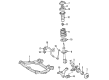
2005 Toyota Highlander Absorber Assembly, Shock
Part Number: 48520-A9220$217.49 MSRP: $310.53You Save: $93.04 (30%)Ships in 1-3 Business DaysProduct Specifications- Other Name: ABSORBER ASSY, SHOCK; Suspension Strut Assembly Kit; Shock Absorber
- Position: Driver Side
- Replaces: 48520-49555
- Item Weight: 15.70 Pounds
- Item Dimensions: 28.5 x 8.6 x 8.0 inches
- Condition: New
- SKU: 48520-A9220
- Warranty: This genuine part is guaranteed by Toyota's factory warranty.

2005 Toyota Highlander Strut Assembly, Passenger Side
Part Number: 48510-A9360$189.07 MSRP: $269.94You Save: $80.87 (30%)Ships in 1-3 Business DaysProduct Specifications- Other Name: Absorber Set, Shock; Suspension Strut Assembly Kit; Complete Strut Kit; Complete Strut; Shock Absorber; Strut
- Position: Passenger Side
- Replaces: 48510-49445
- Item Weight: 15.70 Pounds
- Item Dimensions: 26.9 x 8.9 x 7.6 inches
- Condition: New
- SKU: 48510-A9360
- Warranty: This genuine part is guaranteed by Toyota's factory warranty.


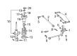
2005 Toyota Highlander Strut, Rear Driver Side
Part Number: 48540-49245$162.84 MSRP: $230.53You Save: $67.69 (30%)Ships in 1-3 Business DaysProduct Specifications- Other Name: Absorber Assembly, Shock; Rear Left Suspension Strut; Complete Strut Kit; Shock Absorber; Absorber Assembly, Shock, Rear Driver Side
- Manufacturer Note: MARK 48540-48210
- Position: Rear Driver Side
- Part Name Code: 48540
- Item Weight: 14.20 Pounds
- Item Dimensions: 26.6 x 6.8 x 5.7 inches
- Condition: New
- Fitment Type: Direct Replacement
- SKU: 48540-49245
- Warranty: This genuine part is guaranteed by Toyota's factory warranty.

2005 Toyota Highlander Strut, Rear Passenger Side
Part Number: 48530-49415$162.84 MSRP: $230.53You Save: $67.69 (30%)Ships in 1-3 Business DaysProduct Specifications- Other Name: Absorber Assembly, Shock; Rear Right Suspension Strut; Complete Strut Kit; Shock Absorber; Absorber Assembly, Shock, Rear Passenger Side
- Manufacturer Note: MARK 48530-48200
- Position: Rear Passenger Side
- Part Name Code: 48530
- Item Weight: 13.30 Pounds
- Item Dimensions: 25.8 x 6.5 x 5.7 inches
- Condition: New
- Fitment Type: Direct Replacement
- SKU: 48530-49415
- Warranty: This genuine part is guaranteed by Toyota's factory warranty.


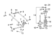
2005 Toyota Highlander Strut, Rear Passenger Side
Part Number: 48530-49555$160.61 MSRP: $227.36You Save: $66.75 (30%)Ships in 1-3 Business DaysProduct Specifications- Other Name: Absorber Assembly, Front Right-Hand; Rear Right Suspension Strut; Strut Assembly Kit; Shock Absorber; Absorber Assembly, Shock, Rear Passenger Side
- Manufacturer Note: MARK 48530-48230
- Position: Rear Passenger Side
- Part Name Code: 48530
- Item Weight: 12.30 Pounds
- Item Dimensions: 26.1 x 6.8 x 5.8 inches
- Condition: New
- Fitment Type: Direct Replacement
- SKU: 48530-49555
- Warranty: This genuine part is guaranteed by Toyota's factory warranty.


2005 Toyota Highlander Strut, Rear Driver Side
Part Number: 48540-49295$156.15 MSRP: $221.04You Save: $64.89 (30%)Ships in 1-3 Business DaysProduct Specifications- Other Name: Absorber Assembly, Front Left-Hand; Rear Left Suspension Strut; Strut Assembly Kit; Shock Absorber; Absorber Assembly, Shock, Rear Driver Side
- Manufacturer Note: MARK 48540-48230
- Position: Rear Driver Side
- Part Name Code: 48540
- Item Weight: 12.80 Pounds
- Item Dimensions: 25.6 x 6.8 x 5.9 inches
- Condition: New
- Fitment Type: Direct Replacement
- SKU: 48540-49295
- Warranty: This genuine part is guaranteed by Toyota's factory warranty.
2005 Toyota Highlander Shock Absorber
Looking for affordable OEM 2005 Toyota Highlander Shock Absorber? Explore our comprehensive catalogue of genuine 2005 Toyota Highlander Shock Absorber. All our parts are covered by the manufacturer's warranty. Plus, our straightforward return policy and speedy delivery service ensure an unparalleled shopping experience. We look forward to your visit!
2005 Toyota Highlander Shock Absorber Parts Q&A
- Q: How to effectively service and repair the shock absorber in the rear strut assembly on 2005 Toyota Highlander?A: Begin all rear strut service and repair operations by supporting the rear axle carrier with a jack for both 2WD and 4WD vehicles. Start by first removing the deck side trim cover LH and the rear wheel but separate the rear stabilizer link assembly LH by disconnecting it from the shock absorber through nut removal using a hexagon wrench (5 mm) when the ball joint spins with the nut. Service 2WD models by first removing the skid control sensor connector before taking out two bolts which allows the flexible hose separation from the shock absorber and skid control sensor wire from the rear axle carrier. Recovery of the 3 bolts allows you to disconnect both the flexible hose and speed sensor for 4WD models. First loosen the 2 nuts on the shock absorber's bottom while keeping the nuts installed then install a jack beneath the rear axle carrier before removing the 3 nuts. Take out the shock absorber with coil spring by removing the rear axle carrier first and afterward the two lower shock absorber nuts and bolts. It is necessary to place the shock absorber bracket with 2 nuts and bolt at its lower part in a vise after assembly. The installation of Special Service Tool: 09727-30021 (09727-00010, 09727-00021, 09727-00031)s requires jack compression of the coil spring by loosening the shock absorber assembly rear LH nut before securing the LH support suspension with a taped-up bar to prevent stud bolt damage. The service technician should first remove the nut along with collar and LH support suspension but next in sequence should remove the coil spring and spring bumper and insulator lower. The shock absorber assembly rear LH requires inspection through rod compression and extension to detect any abnormal resistance or unwarranted sounds before initiating a replacement if defects are present. Place the spring bumper and insulator lower into position followed by compression of the coil spring with the same special service tool before placing the coil spring onto the shock absorber where its lower end should rest within the lower seat gap. Insert the lower bracket of the LH support suspension to the shock absorber position 3.5 degrees in front of the vehicle while fitting a collar to the piston rod before removing the special service tool. Tighten the nut fully as you hold the LH support suspension with a bar taped up to reach 49 Nm (500 kgf-cm, 36 ft. lbs.) while adjusting the nut under torque. The shock absorber installation requires 3 nuts tightened up to 58 Nm (590 kgf-cm, 43 ft-lbs) followed by 2 bolt and nut torqueing to 180 Nm (1,840 kgf-cm, 133 ft-lbs). The fitting process must prevent bolt rotation. The installation process requires 2WD models to bolt the flexible hose and skid control sensor wire using two fasteners to join the skid control sensor connector while applying 19 Nm (192 kgf-cm, 14 ft. lbs.) torque for A screw but only 5.0 Nm (51 kgf-cm, 44 inch lbs.) torque for B screw. The flexible hose assembly with speed sensor needs three bolts installation for 4WD models. Torque settings should be 5.0 Nm (51 kgf-cm, 44 inch lbs.) for Bolt A and 19 Nm (192 kgf-cm, 14 ft. lbs.) for Bolt B with 8.0 Nm (82 kgf-cm, 71 inch lbs.) for Bolt C. Similarly, attach the stabilizer link to the shock absorber with the nut using 39 Nm (400 kgf-cm, 29 ft. lbs.), requiring a 5 mm hexagon wrench Install the rear wheel with a torque of 103 Nm (1,050 kgf-cm, 76 ft. lbs.) while conducting inspections on rear wheel alignment and ABS speed sensor. When disposing of the shock absorber assembly rear LH extension, fully open the rod while drilling a hole between points A and B in the cylinder to release gas content with necessary safety equipment as the procedure may produce metallic material and the pressurized gas is non-toxic, odorless and colorless.
Related 2005 Toyota Highlander Parts
 2005 Toyota Highlander Control Arm
 2005 Toyota Highlander Axle Shaft
 2005 Toyota Highlander Ball Joint
 2005 Toyota Highlander Bump Stop
 2005 Toyota Highlander Coil Spring Insulator
 2005 Toyota Highlander Rear Crossmember
 2005 Toyota Highlander Shock and Strut Boot
 2005 Toyota Highlander Steering Knuckle
 2005 Toyota Highlander Suspension Strut Rod
 2005 Toyota Highlander Sway Bar Bracket
 2005 Toyota Highlander Sway Bar Link
 2005 Toyota Highlander Trailing Arm