×
ToyotaParts- Hello
- Login or Register
- Quick Links
- Live Chat
- Track Order
- Parts Availability
- RMA
- Help Center
- Contact Us
- Shop for
- Toyota Parts
- Scion Parts
My Garage
My Account
Cart
OEM 2004 Toyota Highlander Shock Absorber
Suspension Shock Absorber- Select Vehicle by Model
- Select Vehicle by VIN
Select Vehicle by Model
orMake
Model
Year
Select Vehicle by VIN
For the most accurate results, select vehicle by your VIN (Vehicle Identification Number).
6 Shock Absorbers found


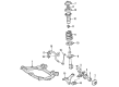
2004 Toyota Highlander Absorber Assembly, Shock
Part Number: 48520-A9220$217.49 MSRP: $310.53You Save: $93.04 (30%)Ships in 1-3 Business DaysProduct Specifications- Other Name: ABSORBER ASSY, SHOCK; Suspension Strut Assembly Kit; Shock Absorber
- Position: Driver Side
- Replaces: 48520-49555
- Item Weight: 15.70 Pounds
- Item Dimensions: 28.5 x 8.6 x 8.0 inches
- Condition: New
- SKU: 48520-A9220
- Warranty: This genuine part is guaranteed by Toyota's factory warranty.

2004 Toyota Highlander Strut Assembly, Passenger Side
Part Number: 48510-A9360$189.07 MSRP: $269.94You Save: $80.87 (30%)Ships in 1-3 Business DaysProduct Specifications- Other Name: Absorber Set, Shock; Suspension Strut Assembly Kit; Complete Strut Kit; Complete Strut; Shock Absorber; Strut
- Position: Passenger Side
- Replaces: 48510-49445
- Item Weight: 15.70 Pounds
- Item Dimensions: 26.9 x 8.9 x 7.6 inches
- Condition: New
- SKU: 48510-A9360
- Warranty: This genuine part is guaranteed by Toyota's factory warranty.


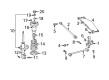
2004 Toyota Highlander Strut, Rear Driver Side
Part Number: 48540-49245$162.84 MSRP: $230.53You Save: $67.69 (30%)Ships in 1-3 Business DaysProduct Specifications- Other Name: Absorber Assembly, Shock; Rear Left Suspension Strut; Complete Strut Kit; Shock Absorber; Absorber Assembly, Shock, Rear Driver Side
- Manufacturer Note: MARK 48540-48210
- Position: Rear Driver Side
- Part Name Code: 48540
- Item Weight: 14.20 Pounds
- Item Dimensions: 26.6 x 6.8 x 5.7 inches
- Condition: New
- Fitment Type: Direct Replacement
- SKU: 48540-49245
- Warranty: This genuine part is guaranteed by Toyota's factory warranty.

2004 Toyota Highlander Strut, Rear Passenger Side
Part Number: 48530-49415$162.84 MSRP: $230.53You Save: $67.69 (30%)Ships in 1-3 Business DaysProduct Specifications- Other Name: Absorber Assembly, Shock; Rear Right Suspension Strut; Complete Strut Kit; Shock Absorber; Absorber Assembly, Shock, Rear Passenger Side
- Manufacturer Note: MARK 48530-48200
- Position: Rear Passenger Side
- Part Name Code: 48530
- Item Weight: 13.30 Pounds
- Item Dimensions: 25.8 x 6.5 x 5.7 inches
- Condition: New
- Fitment Type: Direct Replacement
- SKU: 48530-49415
- Warranty: This genuine part is guaranteed by Toyota's factory warranty.


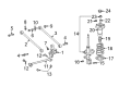
2004 Toyota Highlander Strut, Rear Passenger Side
Part Number: 48530-49555$160.61 MSRP: $227.36You Save: $66.75 (30%)Ships in 1-3 Business DaysProduct Specifications- Other Name: Absorber Assembly, Front Right-Hand; Rear Right Suspension Strut; Strut Assembly Kit; Shock Absorber; Absorber Assembly, Shock, Rear Passenger Side
- Manufacturer Note: MARK 48530-48230
- Position: Rear Passenger Side
- Part Name Code: 48530
- Item Weight: 12.30 Pounds
- Item Dimensions: 26.1 x 6.8 x 5.8 inches
- Condition: New
- Fitment Type: Direct Replacement
- SKU: 48530-49555
- Warranty: This genuine part is guaranteed by Toyota's factory warranty.


2004 Toyota Highlander Strut, Rear Driver Side
Part Number: 48540-49295$156.15 MSRP: $221.04You Save: $64.89 (30%)Ships in 1-3 Business DaysProduct Specifications- Other Name: Absorber Assembly, Front Left-Hand; Rear Left Suspension Strut; Strut Assembly Kit; Shock Absorber; Absorber Assembly, Shock, Rear Driver Side
- Manufacturer Note: MARK 48540-48230
- Position: Rear Driver Side
- Part Name Code: 48540
- Item Weight: 12.80 Pounds
- Item Dimensions: 25.6 x 6.8 x 5.9 inches
- Condition: New
- Fitment Type: Direct Replacement
- SKU: 48540-49295
- Warranty: This genuine part is guaranteed by Toyota's factory warranty.
2004 Toyota Highlander Shock Absorber
Looking for affordable OEM 2004 Toyota Highlander Shock Absorber? Explore our comprehensive catalogue of genuine 2004 Toyota Highlander Shock Absorber. All our parts are covered by the manufacturer's warranty. Plus, our straightforward return policy and speedy delivery service ensure an unparalleled shopping experience. We look forward to your visit!
2004 Toyota Highlander Shock Absorber Parts Q&A
- Q: How to replace the shock absorber assy front LH on 2004 Toyota Highlander?A: Start the shock absorber assy front LH replacement process by taking out the front wheel and disconnecting the front stabilizer link assembly LH by breaking its connection with the shock absorber through nut removal. Stability may be maintained by using a hexagon (6 mm) wrench to stop the ball joint from rotating with the nut. The front shock absorber extraction starts with loosening the locking nut that stays before disconnecting flexible hose and abs speed sensor wire harness bracket followed by removing two lower side nuts and bolts but maintaining bolt stability. Start by removing the upper three nuts followed by disconnecting the shock absorber along with its coil spring which should involve a proper disconnection of the front speed sensor. Fasten the front shock absorber with coil spring inside a vise by installing a double-nutted bolt at its bottom section. The shock absorber removal requires special service tool: 09727-30021 (09727-00010 09727-00021) to compress the coil spring and prevents using an impact wrench because it could damage the tool. Uninstall the shock absorber assembly while removing the front suspension support subassembly LH and its components including the front suspension support bearing LH, front coil spring seat upper LH, front coil spring insulator upper LH, front coil spring LH and front spring bumper LH, front coil spring insulator lower LH. Several test compressions and extensions of the shock absorber rod will help identify any irregular resistance or sounds; replace defective units. One installs the lower insulator onto the shock absorber by next integrating the spring bumper to the piston rod under conditions where a special service tool compresses the coil spring. Install the coil spring starting with the lower end insertion into the bottom spring seat gap and then place the upper insulator and both spring seat into position with the mark visible on the outside. First install a new ball bearing coupled with a suspension support that has the mark pointing outward. Then install a new lock nut temporarily before using the special service tool to gently remove the coil spring. Fasten the shock absorber together with coil spring by installing three upper side nuts that should be tightened to 80 nm (815 kgf-cm, 59 ft. lbs.) after which install two bolts and two lower side nuts torqued to 230 nm (2,350 kgf-cm, 170 ft-lbf) while maintaining bolt rotation control. Secure the flexible hose by mounting a bolt which needs torquing to 18.8 nm (192 kgf-cm, 14 ft. lbs.) followed by full tightening of the lock nut to 49 nm (500 kgf-cm, 36 ft. lbs.). creat a final step by installing the front stabilizer link and its nut while torquing both to 74 nm (755 kgf-cm, 55 ft. lbs.). Reinstall the front wheel through completing the torquing procedure to 103 nm (1,050 kgf-cm, 76 ft. lbs.). The disposal process begins with extending the shock absorber rod and requires drilling a hole into the cylinder to evaporate the gas while keeping chip materials out of the way because the gas contains zero color or odor and has no poisonous elements.
Related 2004 Toyota Highlander Parts
 2004 Toyota Highlander Control Arm
 2004 Toyota Highlander Axle Shaft
 2004 Toyota Highlander Ball Joint
 2004 Toyota Highlander Bump Stop
 2004 Toyota Highlander Coil Spring Insulator
 2004 Toyota Highlander Rear Crossmember
 2004 Toyota Highlander Shock and Strut Boot
 2004 Toyota Highlander Steering Knuckle
 2004 Toyota Highlander Suspension Strut Rod
 2004 Toyota Highlander Sway Bar Bracket
 2004 Toyota Highlander Sway Bar Link
 2004 Toyota Highlander Trailing Arm