×
ToyotaParts- Hello
- Login or Register
- Quick Links
- Live Chat
- Track Order
- Parts Availability
- RMA
- Help Center
- Contact Us
- Shop for
- Toyota Parts
- Scion Parts
My Garage
My Account
Cart
OEM 2004 Toyota Highlander Axle Shaft
Car Axle Shaft- Select Vehicle by Model
- Select Vehicle by VIN
Select Vehicle by Model
orMake
Model
Year
Select Vehicle by VIN
For the most accurate results, select vehicle by your VIN (Vehicle Identification Number).
10 Axle Shafts found


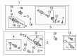
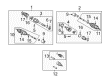
2004 Toyota Highlander Axle Assembly, Driver Side
Part Number: 43420-48091$370.57 MSRP: $543.06You Save: $172.49 (32%)Ships in 1-3 Business DaysProduct Specifications- Other Name: Shaft Assembly, Front Drive; CV Axle Assembly, Front Left; GSP Cv Axle; Axle Shaft; Shaft Assembly, Front Drive, Driver Side; CV Axle Assembly
- Position: Driver Side
- Replaces: 43420-48090
- Part Name Code: 43420
- Item Weight: 6.00 Pounds
- Item Dimensions: 8.7 x 4.6 x 4.3 inches
- Condition: New
- Fitment Type: Direct Replacement
- SKU: 43420-48091
- Warranty: This genuine part is guaranteed by Toyota's factory warranty.

2004 Toyota Highlander Shaft Assembly, Front Drive, Driver Side
Part Number: 43420-0E021$468.29 MSRP: $686.28You Save: $217.99 (32%)Product Specifications- Other Name: Shaft Assembly, Front Drive; CV Axle Assembly; Axle Shaft
- Position: Driver Side
- Replaces: 43420-0E020
- Part Name Code: 43420
- Item Weight: 20.90 Pounds
- Item Dimensions: 28.9 x 6.3 x 6.3 inches
- Condition: New
- Fitment Type: Direct Replacement
- SKU: 43420-0E021
- Warranty: This genuine part is guaranteed by Toyota's factory warranty.

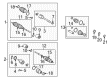
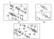
2004 Toyota Highlander Outer CV Joint, Driver Side
Part Number: 42370-49125$301.84 MSRP: $430.96You Save: $129.12 (30%)Ships in 1-3 Business DaysProduct Specifications- Other Name: Shaft Assembly, Rear Drive; CV Joint; Outer Joint; Shaft Assembly, Rear Drive Outboard Joint, Driver Side; Shaft Assembly, Rear Drive Outboard Joint
- Position: Driver Side
- Item Weight: 6.20 Pounds
- Item Dimensions: 8.7 x 4.5 x 4.1 inches
- Condition: New
- Fitment Type: Direct Replacement
- SKU: 42370-49125
- Warranty: This genuine part is guaranteed by Toyota's factory warranty.

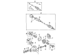
2004 Toyota Highlander Axle Shaft Assembly, Passenger Side
Part Number: 43410-48050$467.72 MSRP: $685.46You Save: $217.74 (32%)Ships in 1-3 Business DaysProduct Specifications- Other Name: Shaft Assembly, Front Drive; CV Axle Assembly, Front Right; GSP Cv Axle; Axle Shaft; Axle Assembly; Shaft Assembly, Front Drive, Passenger Side; CV Axle Assembly
- Position: Passenger Side
- Part Name Code: 43410
- Item Weight: 20.90 Pounds
- Item Dimensions: 43.7 x 5.9 x 5.6 inches
- Condition: New
- Fitment Type: Direct Replacement
- SKU: 43410-48050
- Warranty: This genuine part is guaranteed by Toyota's factory warranty.

2004 Toyota Highlander Axle Assembly, Passenger Side
Part Number: 43410-48061$424.82 MSRP: $622.58You Save: $197.76 (32%)Ships in 1-3 Business DaysProduct Specifications- Other Name: Shaft Assembly, Front Drive; CV Axle Assembly, Front Right; GSP Cv Axle; Axle Shaft; Shaft Assembly, Front Drive, Passenger Side; CV Axle Assembly
- Position: Passenger Side
- Replaces: 43410-48060
- Part Name Code: 43410
- Item Weight: 20.90 Pounds
- Item Dimensions: 44.6 x 5.9 x 5.5 inches
- Condition: New
- Fitment Type: Direct Replacement
- SKU: 43410-48061
- Warranty: This genuine part is guaranteed by Toyota's factory warranty.

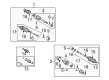
2004 Toyota Highlander Axle Assembly, Driver Side
Part Number: 43420-48100$420.85 MSRP: $616.76You Save: $195.91 (32%)Ships in 1-3 Business DaysProduct Specifications- Other Name: Shaft Assembly, Front Drive; CV Axle Assembly, Front Left; GSP Cv Axle; Axle Shaft; Shaft Assembly, Front Drive, Driver Side; CV Axle Assembly
- Position: Driver Side
- Part Name Code: 43420
- Item Weight: 17.90 Pounds
- Item Dimensions: 31.6 x 5.4 x 5.2 inches
- Condition: New
- Fitment Type: Direct Replacement
- SKU: 43420-48100
- Warranty: This genuine part is guaranteed by Toyota's factory warranty.

2004 Toyota Highlander Axle Assembly, Passenger Side
Part Number: 43410-48071$471.92 MSRP: $691.60You Save: $219.68 (32%)Ships in 1-3 Business DaysProduct Specifications- Other Name: Shaft Assembly, Front Drive; CV Axle Assembly, Front Right; GSP Cv Axle; Axle Shaft; Shaft Assembly, Front Drive, Passenger Side; CV Axle Assembly
- Position: Passenger Side
- Replaces: 43410-48070
- Part Name Code: 43410
- Item Weight: 14.40 Pounds
- Item Dimensions: 30.7 x 7.4 x 6.8 inches
- Condition: New
- Fitment Type: Direct Replacement
- SKU: 43410-48071
- Warranty: This genuine part is guaranteed by Toyota's factory warranty.

2004 Toyota Highlander Axle Shaft Assembly, Rear
Part Number: 42340-48030$380.89 MSRP: $558.21You Save: $177.32 (32%)Ships in 1-3 Business DaysProduct Specifications- Other Name: Shaft Assembly, Rear Drive; CV Axle Assembly, Rear Left, Rear Right; GSP Cv Axle; Axle Shaft; Axle Assembly; Shaft Assembly, Rear Drive, Passenger Side; Shaft Assembly, Rear Drive, Driver Side; CV Axle Assembly
- Position: Rear
- Item Weight: 5.90 Pounds
- Item Dimensions: 8.3 x 4.2 x 4.5 inches
- Condition: New
- Fitment Type: Direct Replacement
- SKU: 42340-48030
- Warranty: This genuine part is guaranteed by Toyota's factory warranty.

2004 Toyota Highlander Axle Shaft Assembly, Driver Side
Part Number: 43420-48061$370.57 MSRP: $543.06You Save: $172.49 (32%)Ships in 1-3 Business DaysProduct Specifications- Other Name: Shaft Assembly, Front Drive; CV Axle Assembly, Front Left; GSP Cv Axle; Axle Shaft; Axle Assembly; Shaft Assembly, Front Drive, Driver Side; CV Axle Assembly
- Position: Driver Side
- Replaces: 43420-48060
- Part Name Code: 43420
- Item Weight: 18.70 Pounds
- Item Dimensions: 31.0 x 5.4 x 5.4 inches
- Condition: New
- Fitment Type: Direct Replacement
- SKU: 43420-48061
- Warranty: This genuine part is guaranteed by Toyota's factory warranty.
 Product Specifications
- Other Name: Shaft Assembly, Front Drive; CV Axle Assembly, Front Right; GSP Cv Axle; Axle Shaft; Axle Assembly; Shaft Assembly, Front Drive, Passenger Side; CV Axle Assembly
- Position: Passenger Side
- Part Name Code: 43410
- Item Weight: 24.50 Pounds
- Item Dimensions: 43.7 x 5.5 x 5.5 inches
- Condition: New
- Fitment Type: Direct Replacement
- SKU: 43410-0W150
- Warranty: This genuine part is guaranteed by Toyota's factory warranty.
2004 Toyota Highlander Axle Shaft
Looking for affordable OEM 2004 Toyota Highlander Axle Shaft? Explore our comprehensive catalogue of genuine 2004 Toyota Highlander Axle Shaft. All our parts are covered by the manufacturer's warranty. Plus, our straightforward return policy and speedy delivery service ensure an unparalleled shopping experience. We look forward to your visit!
2004 Toyota Highlander Axle Shaft Parts Q&A
- Q: How to overhaul the axle shaft assembly on 2004 Toyota Highlander?A: The overhaul process for the axle shaft starts with draining automatic transaxle fluid and removing the front wheel. Apply the brakes to remove the lock nut before you remove the front axle hub LH nut by using Special Service Tool: 09930-00010 with a hammer to unstake it. To disassemble the speed sensor front LH you need to remove its bolt then disconnect both wire and hose from shock absorber while using a hexagon wrench (6 mm) when the ball joint moves with the nut. The tie rod assembly LH requires removal of both the cotter pin and nut to separate it. After which Special Service Tool: 09620-62011 can unfasten the tie rod end from its position on the steering knuckle. It is necessary to remove the bolt and two nuts from the front suspension arm sub-assembly lower No.1 LH to separate it from the lower ball joint. A plastic hammer should be used to separate the front axle assembly LH from the drive shaft while maintaining safety of the boot and speed sensor rotor. Lay the front drive shaft assembly LH in position by first removing the front fender apron seal LH and using Special Service Tool: 09520-01010, 09520-24010 (09520-32040) to detach it while guarding the oil seal from damage. Proceed by first using pliers to remove the snap ring of the front drive shaft assembly RH while detaching the bolt and front drive shaft RH from the bearing bracket followed by a brass bar and hammer application to remove the drive shaft by avoiding damage to the dust cover and oil seal. Fix the front axle assembly LH with Special Service Tool: 09608-16042 (09608-02021, 09608-02041) at hand to sustain the hub bearing while performing maintenance. Validate the outboard joint play in the front drive shaft assembly LH while checking that the inboard joint operates smoothly together with an inspection for damaged boots. Use a soft vise to mount the drive shaft while using hexagon wrenches to detach the bolts and joint washers from the front drive flange shaft sub-assembly without compressing the inboard boot. The installation process should be performed on the differential side gear shaft sub-assembly LH. Use a screwdriver to eliminate the snap ring from the front drive shaft LH hole while using a press to remove the dust covers. Detach the front axle inboard joint boot clamp by using Special Service Tool: 09726-10011 (09726-00031) while ensuring that matchmarks line up precisely during removal of the front drive shaft cross groove joint sub-assembly LH. The technician installs the front axle inboard joint cover LH using FIPG: 08826-00801 while maintaining proper fitting and avoids scratches by hand tightening. Mount the front drive shaft bearing with Special Service Tool: 09527-21011 and a press then add inboard joint boot and dust cover after packing them with specified grease. Driveline professionals should reassemble the front drive shaft cross groove joint sub-assembly LH by properly aligning components and inserting the snap ring. Clamp the front axle inboard joint boots to their proper position while installing dust covers by using a press method without damaging the materials. Fit the new snap ring to the front drive shaft LH hole and differential side gear shaft sub-assembly LH hole while packing them with specified grease before fastening with hexagon bolts at the indicated torque level. The front drive flange shaft sub-assembly requires proper torque and requires another inspection of the front drive shaft assembly LH before installation which includes ATF application on the spline and shaft spline alignment. The front suspension arm sub-assembly lower No.1 LH with tie rod assembly LH requires installation by using specified torque while installing a cotter pin for prevention. You should reinstall the speed sensor front LH assembly after applying correct torque but with caution to protect from damage while also torquing and staking the front axle hub LH assembly afterward. Replace the front wheel then refill with automatic transaxle fluid before checking the fluid level alongside front wheel alignment as well as ABS speed sensor signal.
Related 2004 Toyota Highlander Parts
 2004 Toyota Highlander Control Arm
 2004 Toyota Highlander CV Boot
 2004 Toyota Highlander CV Joint
 2004 Toyota Highlander Coil Springs
 2004 Toyota Highlander Differential Mount
 2004 Toyota Highlander Lateral Link
 2004 Toyota Highlander Rear Crossmember
 2004 Toyota Highlander Sway Bar Bracket
 2004 Toyota Highlander Sway Bar Bushing
 2004 Toyota Highlander Sway Bar Kit
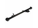 2004 Toyota Highlander Trailing Arm
 2004 Toyota Highlander Transfer Case Output Shaft Snap Ring