×
ToyotaParts- Hello
- Login or Register
- Quick Links
- Live Chat
- Track Order
- Parts Availability
- RMA
- Help Center
- Contact Us
- Shop for
- Toyota Parts
- Scion Parts
My Garage
My Account
Cart
OEM 2003 Toyota Highlander Axle Shaft
Car Axle Shaft- Select Vehicle by Model
- Select Vehicle by VIN
Select Vehicle by Model
orMake
Model
Year
Select Vehicle by VIN
For the most accurate results, select vehicle by your VIN (Vehicle Identification Number).
12 Axle Shafts found


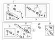
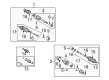
2003 Toyota Highlander Axle Assembly, Driver Side
Part Number: 43420-48091$370.57 MSRP: $543.06You Save: $172.49 (32%)Ships in 1-3 Business DaysProduct Specifications- Other Name: Shaft Assembly, Front Drive; CV Axle Assembly, Front Left; GSP Cv Axle; Axle Shaft; Shaft Assembly, Front Drive, Driver Side; CV Axle Assembly
- Position: Driver Side
- Replaces: 43420-48090
- Part Name Code: 43420
- Item Weight: 6.00 Pounds
- Item Dimensions: 8.7 x 4.6 x 4.3 inches
- Condition: New
- Fitment Type: Direct Replacement
- SKU: 43420-48091
- Warranty: This genuine part is guaranteed by Toyota's factory warranty.

2003 Toyota Highlander Outer CV Joint, Driver Side
Part Number: 42370-49035$273.32 MSRP: $390.24You Save: $116.92 (30%)Ships in 1-3 Business DaysProduct Specifications- Other Name: Shaft Assembly, Rear Drive; CV Joint; Shaft & Joint; Outer Joint; Rear Drive Outboard Joint, Driver Side Assembly
- Position: Driver Side
- Item Weight: 12.60 Pounds
- Item Dimensions: 33.2 x 6.2 x 5.5 inches
- Condition: New
- Fitment Type: Direct Replacement
- SKU: 42370-49035
- Warranty: This genuine part is guaranteed by Toyota's factory warranty.

2003 Toyota Highlander Shaft Sub-Assembly, Differential Side Gear, Driver Side
Part Number: 41309-28030$261.53 MSRP: $373.41You Save: $111.88 (30%)Ships in 1-3 Business DaysProduct Specifications- Other Name: Shaft Sub-Assembly, Differential Side Gear
- Position: Driver Side
- Part Name Code: 41309
- Item Weight: 3.30 Pounds
- Item Dimensions: 6.8 x 7.0 x 5.6 inches
- Condition: New
- Fitment Type: Direct Replacement
- SKU: 41309-28030
- Warranty: This genuine part is guaranteed by Toyota's factory warranty.

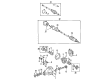
2003 Toyota Highlander Shaft, Rear Axle, Passenger Side
Part Number: 42301-32060$260.13 MSRP: $371.41You Save: $111.28 (30%)Ships in 1-3 Business DaysProduct Specifications- Other Name: Shaft Sub-Assembly, Rear Axle; Shaft, Rear Axle, Driver Side; Wheel Hub Repair Kit; Wheel Hub
- Position: Rear
- Item Weight: 4.40 Pounds
- Item Dimensions: 8.1 x 8.5 x 5.3 inches
- Condition: New
- Fitment Type: Direct Replacement
- SKU: 42301-32060
- Warranty: This genuine part is guaranteed by Toyota's factory warranty.

2003 Toyota Highlander Stub Shaft, Front Passenger Side
Part Number: 43049-28010$529.75 MSRP: $776.35You Save: $246.60 (32%)Ships in 1-3 Business DaysProduct Specifications- Other Name: Shaft Sub-Assembly, Front Drive; Drive Axle Shaft, Front Right; Shaft Sub-Assembly, Front Drive Flange
- Position: Front Passenger Side
- Part Name Code: 43049
- Item Weight: 9.80 Pounds
- Condition: New
- Fitment Type: Direct Replacement
- SKU: 43049-28010
- Warranty: This genuine part is guaranteed by Toyota's factory warranty.

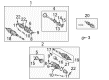
2003 Toyota Highlander Axle Shaft Assembly, Passenger Side
Part Number: 43410-48050$467.72 MSRP: $685.46You Save: $217.74 (32%)Ships in 1-3 Business DaysProduct Specifications- Other Name: Shaft Assembly, Front Drive; CV Axle Assembly, Front Right; GSP Cv Axle; Axle Shaft; Axle Assembly; Shaft Assembly, Front Drive, Passenger Side; CV Axle Assembly
- Position: Passenger Side
- Part Name Code: 43410
- Item Weight: 20.90 Pounds
- Item Dimensions: 43.7 x 5.9 x 5.6 inches
- Condition: New
- Fitment Type: Direct Replacement
- SKU: 43410-48050
- Warranty: This genuine part is guaranteed by Toyota's factory warranty.

2003 Toyota Highlander Axle Assembly, Passenger Side
Part Number: 43410-48061$424.82 MSRP: $622.58You Save: $197.76 (32%)Ships in 1-3 Business DaysProduct Specifications- Other Name: Shaft Assembly, Front Drive; CV Axle Assembly, Front Right; GSP Cv Axle; Axle Shaft; Shaft Assembly, Front Drive, Passenger Side; CV Axle Assembly
- Position: Passenger Side
- Replaces: 43410-48060
- Part Name Code: 43410
- Item Weight: 20.90 Pounds
- Item Dimensions: 44.6 x 5.9 x 5.5 inches
- Condition: New
- Fitment Type: Direct Replacement
- SKU: 43410-48061
- Warranty: This genuine part is guaranteed by Toyota's factory warranty.

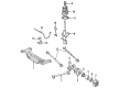
2003 Toyota Highlander Axle Shafts, Rear
Part Number: 42340-48020$418.58 MSRP: $613.43You Save: $194.85 (32%)Ships in 1-3 Business DaysProduct Specifications- Other Name: Shaft Assembly, Rear Drive; CV Axle Assembly, Rear Left, Rear Right; GSP Cv Axle; Axle Shaft; Axle Assembly; Shaft Assembly, Rear Drive, Passenger Side; Shaft Assembly, Rear Drive, Driver Side; CV Axle Assembly
- Position: Rear
- Item Weight: 16.70 Pounds
- Item Dimensions: 28.8 x 8.8 x 7.5 inches
- Condition: New
- Fitment Type: Direct Replacement
- SKU: 42340-48020
- Warranty: This genuine part is guaranteed by Toyota's factory warranty.

2003 Toyota Highlander Axle Assembly, Passenger Side
Part Number: 43410-48071$471.92 MSRP: $691.60You Save: $219.68 (32%)Ships in 1-3 Business DaysProduct Specifications- Other Name: Shaft Assembly, Front Drive; CV Axle Assembly, Front Right; GSP Cv Axle; Axle Shaft; Shaft Assembly, Front Drive, Passenger Side; CV Axle Assembly
- Position: Passenger Side
- Replaces: 43410-48070
- Part Name Code: 43410
- Item Weight: 14.40 Pounds
- Item Dimensions: 30.7 x 7.4 x 6.8 inches
- Condition: New
- Fitment Type: Direct Replacement
- SKU: 43410-48071
- Warranty: This genuine part is guaranteed by Toyota's factory warranty.

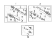
2003 Toyota Highlander Axle Shaft Assembly, Driver Side
Part Number: 43420-48061$370.57 MSRP: $543.06You Save: $172.49 (32%)Ships in 1-3 Business DaysProduct Specifications- Other Name: Shaft Assembly, Front Drive; CV Axle Assembly, Front Left; GSP Cv Axle; Axle Shaft; Axle Assembly; Shaft Assembly, Front Drive, Driver Side; CV Axle Assembly
- Position: Driver Side
- Replaces: 43420-48060
- Part Name Code: 43420
- Item Weight: 18.70 Pounds
- Item Dimensions: 31.0 x 5.4 x 5.4 inches
- Condition: New
- Fitment Type: Direct Replacement
- SKU: 43420-48061
- Warranty: This genuine part is guaranteed by Toyota's factory warranty.
 Product Specifications
- Other Name: Shaft Assembly, Front Drive; CV Axle Assembly, Front Right; Joint Kit, Drive Shaft; GSP Cv Axle; Axle Shaft; Shaft Assembly, Front Drive, Passenger Side; CV Axle Assembly
- Position: Passenger Side
- Replaces: 43410-28050
- Part Name Code: 43410
- Item Weight: 19.90 Pounds
- Item Dimensions: 31.9 x 5.6 x 5.4 inches
- Condition: New
- Fitment Type: Direct Replacement
- SKU: 43410-28051
- Warranty: This genuine part is guaranteed by Toyota's factory warranty.
 Product Specifications
- Other Name: Shaft Assembly, Front Drive; CV Axle Assembly, Front Left; GSP Cv Axle; Axle Shaft; Shaft Assembly, Front Drive, Driver Side; CV Axle Assembly
- Position: Driver Side
- Replaces: 43420-48080
- Part Name Code: 43420
- Item Weight: 18.80 Pounds
- Item Dimensions: 31.0 x 5.3 x 5.2 inches
- Condition: New
- Fitment Type: Direct Replacement
- SKU: 43420-48081
- Warranty: This genuine part is guaranteed by Toyota's factory warranty.
2003 Toyota Highlander Axle Shaft
Looking for affordable OEM 2003 Toyota Highlander Axle Shaft? Explore our comprehensive catalogue of genuine 2003 Toyota Highlander Axle Shaft. All our parts are covered by the manufacturer's warranty. Plus, our straightforward return policy and speedy delivery service ensure an unparalleled shopping experience. We look forward to your visit!
2003 Toyota Highlander Axle Shaft Parts Q&A
- Q: How to overhaul the axle shaft assembly on 2003 Toyota Highlander?A: The overhaul process of the axle shaft assembly starts by draining automatic transaxle fluid and 4WD transfer oil with subsequent use of Special Service Tool: 09930-00010 and hammer access to unstake the front axle hub LH nut while applying brakes before removing the lock nut. First remove the bolt on the front stabilizer link assembly LH before severing its connection to the shock absorber sensor wire and hose using a hexagon wrench (6 mm) on the ball joint when the nut turns. Finish the speed sensor front LH separation by removing its bolt and disconnecting it from the steering knuckle, then detach the tie rod assembly LH through removing the cotter pin and nut while employing Special Service Tool: 09628-62011 to detach the tie rod end from the steering knuckle. Use a plastic hammer to detach the drive shaft from axle hub in the front axle assembly LH after removing two nuts and the bolt and then separate the front suspension arm sub-assembly lower No.1 LH by taking out the bolt and two nuts. During this step make sure to avoid damaging the speed sensor rotor and boot. The front drive shaft assembly LH requires removal through steps which start by disassembling the front fender apron seal LH while using Special Service Tool: 09520-01010, 09520-24010 (09520-32040) to detach it with care for the oil seal. First remove the front fender apron seal RH from the 2WD front drive shaft assembly RH then unbolt the two attaching hardware and withdraw the shaft with center bearing bracket. When working with the front drive shaft assembly on the RH side (4WD vehicles) perform operations as done on the LH side. Use Special Service Tool 09608-16042 (09600-02021, 09608-02041) to support the front axle assembly LH when needed for preventing hub bearing damage. Check the front drive shaft assembly LH by inspecting its outboard joint for movement and inboard joint for effortless sliding and examining boots for damage at regular assembly level. The front axle inboard joint boot requires screwdriver removal of its clamp to disassemble the front axle inboard joint boot from the front drive inboard joint assembly LH. This process begins with shaft marking on the tripod and inboard and outboard components followed by removing the inboard joint shaft from the outboard joint shaft using a snap ring expander tool. Begin by marking the outboard joint shaft together with the tripod. After that, a brass bar with a hammer should be used to extract the tripod from the drive shaft without striking the roller. First detach the drive shaft damper using clamp unstaking followed by taking it off before unstaking each of the four joint boot clamps to take out the outboard joint boot. The LH front drive shaft hole snap ring must be removed with a screwdriver before using Special Service Tool: 09950-00020 and a press machine to extract dust covers for 2WD and 4WD vehicles from both sides. A screwdriver removes the drive shaft bearing snap ring in 2WD models for subsequent separation from the drive shaft bearing case using a press (2WD). Install the new bearing of the front drive shaft bearing (2WD) by using Special Service Tool: 09527-10011 and a press followed by the new bearing assembly with the snap ring using the same tools. Use Special Service Tool 09950-00020 together with a press to install the front drive shaft dust cover (2WD) while ensuring a measurement of 91.5 plus or minus 0.5 mm (3.6 plus or minus 0.02 inch) between the drive shaft tip and dust cover. Repeat this installation process on the right-hand side. The service technician installs the front drive shaft dust cover LH with Special Service Tool: 09527-10011 and a press before fitting the front drive shaft LH hole snap ring and outboard joint boot through temporary clamp applications and joint shaft/boots grease packing at 262-277 g (9.2-9.7 oz). Latch the outboard joint boot clamps with 0.8mm or less clearance while installing the drive shaft damper at 204.4 plus or minus 2.0mm (8.047 plus or minus 0.079 inch) distance. To install the front drive inboard joint assembly left hand side first align the matchmarks while tapping in the tripod before applying grease (185 - 195 g or 6.5 - 6.9 oz.) to the outboard joint shaft and boot and putting in a new snap ring. The front axle inboard joint boot requires installation alongside its boot clamp while ensuring proper engagement. To inspect the front drive shaft you must check its outboard joint play while the assembly remains level then verify smooth sliding motion of the inboard joint and examine both boots for damage. Before inserting the inboard joint shaft assembly construct the spline with ATF and deploy a brass bar together with a hammer to install the front drive shaft assembly LH while maintaining the snap ring with its opening side oriented downwards to prevent oil seal damage. The front drive shaft assembly RH (2WD) requires gear oil on the spline before alignment and two bolt installation (Torque: 64 Nm or 47 ft. lbs.) while maintaining safe handling of the oil seal. Perform the same RH 4WD procedures which apply to the LH side. The starting process begins with enacting the front axle assembly LH while maintaining the outboard joint boot and speed sensor rotor intact. The installation continues with the front suspension arm sub-assembly lower No.1 LH bolted with the nut (127 Nm Torque & 94 ft. lbs.) followed by the tie rod assembly LH (Torque: 49 Nm & 36 ft. lbs.) which requires a new cotter pin application. Additional torque adjustment of the nut to 60 degrees may be necessary. The installation of the speed sensor front LH requires connecting the flexible hose to the shock absorber while using a Torque of 19 Nm or 14 ft. lbs. and securing the speed sensor to the steering knuckle at 8.0 Nm or 71 inch lbs. Perform these tasks with caution to avoid sensor damage and prevent attachment of foreign matter. Install the front stabilizer link assembly LH with a torque of 74 Nm (55 ft. lbs.) before you install the front axle hub LH nut with 294 Nm (217 ft. lbs.) tension and secure it with stakes then put on the front wheel using 103 Nm (76 ft. lbs.) torque while also adding automatic transaxle fluid with an inspection and transfer oil for 4WD with another check followed by front wheel alignment adjustment and ABS speed sensor signal examination.
Related 2003 Toyota Highlander Parts
 2003 Toyota Highlander Control Arm
 2003 Toyota Highlander CV Boot
 2003 Toyota Highlander CV Joint
 2003 Toyota Highlander Coil Springs
 2003 Toyota Highlander Differential Mount
 2003 Toyota Highlander Lateral Link
 2003 Toyota Highlander Rear Crossmember
 2003 Toyota Highlander Sway Bar Bracket
 2003 Toyota Highlander Sway Bar Bushing
 2003 Toyota Highlander Sway Bar Kit
 2003 Toyota Highlander Transfer Case Output Shaft Snap Ring
 2003 Toyota Highlander Wheel Seal