×
ToyotaParts- Hello
- Login or Register
- Quick Links
- Live Chat
- Track Order
- Parts Availability
- RMA
- Help Center
- Contact Us
- Shop for
- Toyota Parts
- Scion Parts
My Garage
My Account
Cart
OEM 2004 Toyota Sequoia Rack And Pinion
Steering Rack And Pinion- Select Vehicle by Model
- Select Vehicle by VIN
Select Vehicle by Model
orMake
Model
Year
Select Vehicle by VIN
For the most accurate results, select vehicle by your VIN (Vehicle Identification Number).
2 Rack And Pinions found

2004 Toyota Sequoia Rack, Front
Part Number: 44204-0C011$580.43 MSRP: $850.63You Save: $270.20 (32%)Ships in 1-3 Business DaysProduct Specifications- Other Name: Rack Sub-Assembly, Power; Rack And Pinion Rack Gear, Front; Steering Gearbox; Steering Rack; Rack Sub-Assembly, Power Steering
- Position: Front
- Part Name Code: 44204
- Item Weight: 5.70 Pounds
- Item Dimensions: 32.1 x 3.3 x 2.8 inches
- Condition: New
- Fitment Type: Direct Replacement
- SKU: 44204-0C011
- Warranty: This genuine part is guaranteed by Toyota's factory warranty.

2004 Toyota Sequoia Steering Gear
Part Number: 44250-0C041$722.76 MSRP: $1059.21You Save: $336.45 (32%)Product Specifications- Other Name: Gear Assembly, Power Steering; Rack and Pinion Assembly; Steering Gearbox; Rack & Pinion; Gear Assembly; Gear Assembly, Power Steering(For Rack & Pinion)
- Manufacturer Note: W(REAR STABILIZER)
- Replaces: 44250-0C050, 44250-0C020
- Part Name Code: 44250
- Item Weight: 1.40 Pounds
- Item Dimensions: 3.4 x 3.2 x 3.5 inches
- Condition: New
- Fitment Type: Direct Replacement
- SKU: 44250-0C041
- Warranty: This genuine part is guaranteed by Toyota's factory warranty.
2004 Toyota Sequoia Rack And Pinion
Looking for affordable OEM 2004 Toyota Sequoia Rack And Pinion? Explore our comprehensive catalogue of genuine 2004 Toyota Sequoia Rack And Pinion. All our parts are covered by the manufacturer's warranty. Plus, our straightforward return policy and speedy delivery service ensure an unparalleled shopping experience. We look forward to your visit!
2004 Toyota Sequoia Rack And Pinion Parts Q&A
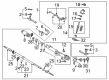
- Q: How to service and repair the Rack And Pinion on 2004 Toyota Sequoia?A: The first step for servicing and repairing the rack and pinion involves the removal of the 2 turn pressure tubes using Special Service Tool: 09023-38400 and the subsequent removal of 4 O-rings. A vise secured rack and pinion assembly requires Special Service Tool: 09612-00012 as well as 2 bolts (90105-10346) and nuts (90170-10198) for stability. Write down marks on the tie rod ends followed by lock nuts and rack ends before removing and loosening them. Use a screwdriver to loosen the 2 clamps which will enable the removal of RH and LH clips and rack boots and clamps without damaging the boot materials. Use a screwdriver with hammer to unstake the claw washers followed by using a spanner to hold the rack and pinion before removing the rack ends using Special Service Tool: 09922-10010. Use the same tool to unlock the rack guide spring cap lock nut followed by removing the rack guide spring cap then rack guide spring and finally the rack guide sub-assembly by using a hexagon wrench. You can remove the rack housing cap using Special Service Tool 09816-30010 and successfully stop the control valve shaft rotation using Special Service Tool 09616-00011 to remove the self-locking nut. First identify the matchmarks before removing the dust cover and control valve housing with its assembly while taking note of the gasket. The valve shaft must be taped with vinyl before press-out using the oil seal while keeping a shop rag between blocks and valve housing to protect the oil seal lip. Use Special Service Tool: 09631-16010 to remove the oil seal and cylinder end stopper before pressing out the rack and pinion with its bushing by utilizing Special Service Tool: 09950-70010 (09951-07200). Steer rack quality assessment includes examining runout and tooth wear and damage conditions wherein necessary replacements involve Special Service Tools: 09950-60010 (09951-00250) and 09950-70010 (09951-07150). To replace the bearings use identical tools and install the oil seal from the bushing with Special Service Tool: 09527-20011 while being cautious not to harm the bushing. Install new teflon rings and O-rings onto the rack and pinion by applying power steering fluid before moving onto the control valve assembly. Keep the rack and pinion free of power steering fluids or molybdenum disulfide lithium base grease then use Special Service Tool: 09950-60010 (09951-00330, 09951-00490, 09952-06010) to install the oil seal before putting the rack inside its housing without disturbing the seal lip. After installing both the bushing and cylinder end stopper technicians need to perform an air tightness test by using Special Service Tool: 09631-12071. The installation of the control valve assembly should include oil seal lip damage prevention followed by oil seal pressing with Special Service Tool: 09612-22011. Thread the control valve housing into position with its new gasket and apply 18 Nm torque to the bolts while the sealing nut should get torqued at 25 Nm. Seal the dust cover and rack housing cap using Part No.08833-00080, Three Bond 1344, Loctite 242 or equivalent paste then secure it with a torque of 59 Nm (600 kgf-cm, 43 ft. lbs.) and stake the cap. The rack guide sub-assembly and rack guide spring and spring cap must be installed for total preload adjustment to manufacturing parameters. The mechanical work proceeds by installing RH and LH claw washers and rack ends at 76 Nm (770 kgf-cm, 56 ft. lbs.) and completing with RH and LH tie rod ends secured with lock nuts. The last step involves applying 13 Nm (135 kgf-cm, 10 ft. lbs.) torque to the 2 turn pressure tubes.
Related 2004 Toyota Sequoia Parts
 2004 Toyota Sequoia Power Steering Pump
 2004 Toyota Sequoia Steering Angle Sensor
 2004 Toyota Sequoia Steering Wheel
 2004 Toyota Sequoia Drag Link
 2004 Toyota Sequoia Power Steering Control Valve
 2004 Toyota Sequoia Power Steering Hose
 2004 Toyota Sequoia Power Steering Reservoir
 2004 Toyota Sequoia Rack and Pinion Boot
 2004 Toyota Sequoia Steering Column Cover
 2004 Toyota Sequoia Steering Gear Box
 2004 Toyota Sequoia Steering Shaft
 2004 Toyota Sequoia Tie Rod End