×
ToyotaParts- Hello
- Login or Register
- Quick Links
- Live Chat
- Track Order
- Parts Availability
- RMA
- Help Center
- Contact Us
- Shop for
- Toyota Parts
- Scion Parts
My Garage
My Account
Cart
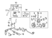
OEM 2004 Toyota Sequoia Power Steering Pump
Power Steering Pump Unit- Select Vehicle by Model
- Select Vehicle by VIN
Select Vehicle by Model
orMake
Model
Year
Select Vehicle by VIN
For the most accurate results, select vehicle by your VIN (Vehicle Identification Number).
1 Power Steering Pump found


 Product Specifications
- Other Name: Pump Assembly, Vane
- Replaces: 44320-0C020, 44320-0C030
- Part Name Code: 44320
- Item Weight: 8.30 Pounds
- Item Dimensions: 10.5 x 7.3 x 7.1 inches
- Condition: New
- Fitment Type: Direct Replacement
- SKU: 44310-0C030
- Warranty: This genuine part is guaranteed by Toyota's factory warranty.
2004 Toyota Sequoia Power Steering Pump
Looking for affordable OEM 2004 Toyota Sequoia Power Steering Pump? Explore our comprehensive catalogue of genuine 2004 Toyota Sequoia Power Steering Pump. All our parts are covered by the manufacturer's warranty. Plus, our straightforward return policy and speedy delivery service ensure an unparalleled shopping experience. We look forward to your visit!
2004 Toyota Sequoia Power Steering Pump Parts Q&A
- Q: How to service and repair the Power Steering Pump on 2004 Toyota Sequoia?A: The first step for Power Steering Pump service requires measuring rotating torque on the PS vane pump until it rotates freely without noise while verifying the torque with a torque wrench shows values under 0.28 Nm (2.8 kgf-cm, 2.4 inch lbs.). Start the power steering pump maintenance by removing the suction port union bolt and its O-ring then proceeding to take off the pressure port union followed by the flow control valve and spring while also extracting the O-ring from the pressure port union. The next step requires removing the 4 housing bolts before proceeding to gently tap the rear housing with a plastic hammer if necessary to separate the wave washer and side plate. Proceed to remove the O-rings from both rear housing openings while also disassembling the wave washer and side plate and gasket and cam ring together with the 10 vane plates and vane pump rotor. Handle all plates with special care to avoid drops. Extract the vane pump shaft which includes the vane pump pulley followed by removal of the 2 straight pins from the front housing. To test the vane pump shaft's oil clearance against its bushing position you must use a micrometer and caliper gauge as the allowable standard range is 0.03 to 0.05 mm (0.0012 to 0.0020 inch) while the maximum limit is set at 0.07 mm (0.0028 inch); replace both the shaft and front housing when the clearance reaches above maximum. The inspection of vane pump rotor and vane plates must verify their height at 8.6 mm (0.339 inch) and thickness at 1.397 mm (0.0550 inch) and length at 14.991 mm (0.5902 inch) with a groove to plate clearance less than 0.033 mm (0.0013 inch). Follow these steps to inspect the flow control valve: apply power steering fluid to its surface then test its movement into the valve hole; check the end hole leak with compressed air at 392 - 490 kPa (4 - 5 kgf/cm2, 57 - 71 psi) and replace the valve with another having the same letter inscribed on the front housing. Verity the spring's untamed length using vernier calipers which must exceed 33.2 mm (1.307 inch). Any spring failing this measurement should be replaced. Use Special Service Tool: 09950-60010 (09951-00330), 09950-70010 (09951-07100) to insert a new oil seal after wrapping the screwdriver with vinyl tape for careful removal and coating the new oil seal lip with power steering fluid while ensuring proper insertion direction. The installer should use power steering fluid to treat indicated components before putting on the vane pump shaft with pulley and hitting 2 new straight pins into the front housing with a plastic hammer. First install the cam ring with its inscribed mark facing outward, then position it correctly with straight pins before adding the vane pump rotor with a new snap ring and facing its inscribed mark outward. The installation requires 10 vane plates facing outward with their round ends and a fresh gasket being applied to the front housing while paying attention to the gasket direction. Install the side plate on the straight pins before putting the wave washer into the slots while making sure the protrusions fit correctly and then apply power steering fluid to two new O-rings before setting them into the rear housing. Begin by securing the rear housing with 4 bolts fastened to 24 Nm (240 kgf-cm, 17 ft. lbs.), and then mount the spring followed by the flow control valve with correct orientation. Cover a new O-ring with power steering fluid before attachment to the pressure port union which should be torqued to 83 Nm (850 kgf-cm, 61 ft. lbs.). Finish by installing the suction port union with new O-ring coated in power steering fluid, torquing the bolt to 13 Nm (130 kgf-cm, 9 ft. lbs.). Place a new O-ring within power steering fluid before you mount it on the suction port union. Secure this union using its bolt and tighten it to 13 Nm (130 kgf-cm, 9 ft. lbs.). Confirm the PS vane pump rotating torque measurement.
Related 2004 Toyota Sequoia Parts
 2004 Toyota Sequoia Steering Wheel
 2004 Toyota Sequoia Rack And Pinion
 2004 Toyota Sequoia Drag Link
 2004 Toyota Sequoia Power Steering Control Valve
 2004 Toyota Sequoia Power Steering Hose
 2004 Toyota Sequoia Power Steering Reservoir
 2004 Toyota Sequoia Rack and Pinion Boot
 2004 Toyota Sequoia Steering Column Cover
 2004 Toyota Sequoia Steering Gear Box
 2004 Toyota Sequoia Steering Shaft
 2004 Toyota Sequoia Tie Rod End
 2004 Toyota Sequoia Wiper Switch