×
ToyotaParts- Hello
- Login or Register
- Quick Links
- Live Chat
- Track Order
- Parts Availability
- RMA
- Help Center
- Contact Us
- Shop for
- Toyota Parts
- Scion Parts
My Garage
My Account
Cart
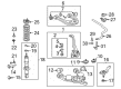
OEM 2002 Toyota Tundra Control Arm
Suspension Arm- Select Vehicle by Model
- Select Vehicle by VIN
Select Vehicle by Model
orMake
Model
Year
Select Vehicle by VIN
For the most accurate results, select vehicle by your VIN (Vehicle Identification Number).
4 Control Arms found


2002 Toyota Tundra Lower Control Arm, Passenger Side
Part Number: 48068-34020$232.56 MSRP: $332.04You Save: $99.48 (30%)Ships in 1-2 Business DaysProduct Specifications- Other Name: Arm Sub-Assembly, Suspension; Suspension Control Arm, Front Right Lower; Arm Sub-Assembly, Front Suspension, Lower Passenger Side; Suspension Control Arm; Control Arm
- Position: Passenger Side
- Replaces: 48068-34030
- Part Name Code: 48068
- Item Weight: 18.10 Pounds
- Item Dimensions: 22.8 x 5.9 x 17.6 inches
- Condition: New
- Fitment Type: Direct Replacement
- SKU: 48068-34020
- Warranty: This genuine part is guaranteed by Toyota's factory warranty.


2002 Toyota Tundra Upper Control Arm, Driver Side
Part Number: 48630-34010$218.78 MSRP: $312.36You Save: $93.58 (30%)Ships in 1-2 Business DaysProduct Specifications- Other Name: Arm Assembly, Suspension; Suspension Control Arm, Front Left Upper; Arm Assembly, Front Suspension, Upper Driver Side; Suspension Control Arm; Control Arm
- Position: Upper Driver Side
- Part Name Code: 48630
- Item Weight: 5.90 Pounds
- Item Dimensions: 16.1 x 3.5 x 12.9 inches
- Condition: New
- Fitment Type: Direct Replacement
- SKU: 48630-34010
- Warranty: This genuine part is guaranteed by Toyota's factory warranty.

2002 Toyota Tundra Upper Control Arm, Passenger Side
Part Number: 48610-34010$238.58 MSRP: $340.63You Save: $102.05 (30%)Ships in 1-2 Business DaysProduct Specifications- Other Name: Arm Assembly, Suspension; Suspension Control Arm, Front Right Upper; Arm Assembly, Front Suspension Upper, Passenger Side; Suspension Control Arm; Control Arm
- Position: Passenger Side
- Part Name Code: 48610
- Item Weight: 6.00 Pounds
- Item Dimensions: 16.1 x 3.6 x 12.7 inches
- Condition: New
- Fitment Type: Direct Replacement
- SKU: 48610-34010
- Warranty: This genuine part is guaranteed by Toyota's factory warranty.

2002 Toyota Tundra Lower Control Arm, Driver Side
Part Number: 48069-34020$230.03 MSRP: $328.43You Save: $98.40 (30%)Product Specifications- Other Name: Arm Sub-Assembly, Suspension; Suspension Control Arm, Front Left Lower; Arm Sub-Assembly, Front Suspension, Lower Driver Side; Suspension Control Arm; Control Arm
- Position: Lower Driver Side
- Replaces: 48069-34030
- Part Name Code: 48069
- Item Weight: 18.00 Pounds
- Item Dimensions: 22.4 x 5.9 x 17.6 inches
- Condition: New
- Fitment Type: Direct Replacement
- SKU: 48069-34020
- Warranty: This genuine part is guaranteed by Toyota's factory warranty.
2002 Toyota Tundra Control Arm
Looking for affordable OEM 2002 Toyota Tundra Control Arm? Explore our comprehensive catalogue of genuine 2002 Toyota Tundra Control Arm. All our parts are covered by the manufacturer's warranty. Plus, our straightforward return policy and speedy delivery service ensure an unparalleled shopping experience. We look forward to your visit!
2002 Toyota Tundra Control Arm Parts Q&A
- Q: How to service and repair the lower control arm on 2002 Toyota Tundra?A: Service and repair of the lower control arm begins with removing the RH and LH front wheels and then proceeding to disconnect RH and LH tie rod ends after removing cotter pins and nuts. Then use Special Service Tool: 09610-20012 to separate tie rod ends from the ball joint while repeating the steps across both sides. First remove power steering gear set bolts along with nuts then disconnect the stabilizer bar link from the lower suspension arm by unfastening the nut; in case the ball joint turns with the nut operation use a hexagon (6 mm) wrench to grip the stud. To disconnect the shock absorber from the lower suspension arm use a lower side set nut and washer to remove the bolt and vinyl tape to protect the drive shaft boot before pulling down on the lower suspension arm. Disassemble the lower ball joint from the lower suspension arm through the removal of the cotter pin and nut followed by the use of Special Service Tool: 09628-62011. The proper removal sequence for the lower suspension arm includes matchmarking the front and rear cam plates and chassis frame followed by extracting the 2 cam plates, bolts, cams along with the lower suspension arm by gently pushing back the power steering gear without breaking power steering tubes. To install a new No.1 bushing employ the combination of Special Service Tool: 09502-12010 and 09631-12090 along with a press and steel plate for setting the correct direction. To install the new No. 2 bushing prepare a steel plate together with Special Service Tool: 09631-12090 and 09950-60020 (09951-00680) followed by employing a press in correct orientation. The process to install or replace the No. 1 and No. 2 spring bumpers on the vehicle involves removing the front wheel then using Special Service Tool: 09922-10010 to change the No. 1 spring bumper at 23 Nm (235 kgf-cm, 17 ft. lbs.) torque with a torque wrench at 345 mm (13.58 inch) fulcrum length before moving to the No. 2 spring bumper replacement that requires removal of the stabilizer bar followed by using the same tool then reinstalling the stabilizer bar and front wheel at 110 Nm (1, To install lower suspension arm onto the chassis frame connect the 2 cams with bolts and cam plates by moving the power steering gear slightly back then secure with 130 Nm (1,325 kgf-cm, 96 ft. lbs.) torque while aligning the matchmarks on front and rear cam plates. The installation requires attachment of the lower ball joint to the lower suspension arm followed by inserting a new nut and cotter pin which should be torqued to 140 Nm (1,450 kgf-cm, 103 ft. lbs.), while advancing tightening to 60 degrees when the cotter pin holes do not align properly. The shock absorber requires a torque of 135 Nm (1,400 kgf-cm, 100 ft. lbs.) to connect it to the lower suspension arm. While doing so, attach the stabilizer bar link to the lower suspension arm using a torque of 69 Nm (700 kgf-cm, 51 ft. lbs.) and use a hexagon (6 mm) wrench for assistance if needed. Install the power steering gear, applying a torque of 165 Nm (1,700 kgf-cm, 122 ft. lbs.) for bolt A, 130 Nm (1,350 kgf-cm, 96 ft. lbs.) for nut B, and 165 Nm (1,700 kgf-cm, 122 ft. lbs.) for bolt and nut C. Connect the RH and LH tie rod ends to the lower ball joints with the nuts and new cotter pins, applying a torque of 91 Nm (930 kgf-cm, 67 ft. lbs.) and tightening further up to 60 degrees if the cotter pin holes are misaligned, then install the RH and LH front wheels with a torque of 110 Nm (1,150 kgf-cm, 83 ft. lbs.) and check the front wheel alignment.
Related 2002 Toyota Tundra Parts
 2002 Toyota Tundra Ball Joint
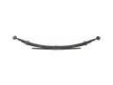 2002 Toyota Tundra Leaf Spring
 2002 Toyota Tundra Steering Knuckle
 2002 Toyota Tundra Sway Bar Link
 2002 Toyota Tundra Sway Bar Kit
 2002 Toyota Tundra Alignment Bolt
 2002 Toyota Tundra Front Cross-Member
 2002 Toyota Tundra Shock Absorber
 2002 Toyota Tundra Strut Housing
 2002 Toyota Tundra Sway Bar Bracket
 2002 Toyota Tundra Sway Bar Bushing
 2002 Toyota Tundra Wheel Seal