×
ToyotaParts- Hello
- Login or Register
- Quick Links
- Live Chat
- Track Order
- Parts Availability
- RMA
- Help Center
- Contact Us
- Shop for
- Toyota Parts
- Scion Parts
My Garage
My Account
Cart
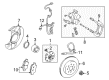
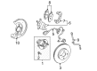
OEM 2002 Toyota MR2 Spyder Brake Caliper
Caliper- Select Vehicle by Model
- Select Vehicle by VIN
Select Vehicle by Model
orMake
Model
Year
Select Vehicle by VIN
For the most accurate results, select vehicle by your VIN (Vehicle Identification Number).
4 Brake Calipers found

2002 Toyota MR2 Spyder Caliper Assembly, Rear Driver Side
Part Number: 47750-17120$276.91 MSRP: $395.36You Save: $118.45 (30%)Ships in 1-3 Business DaysProduct Specifications- Other Name: Cylinder Assembly, Disc; Disc Brake Caliper, Rear Left; Caliper; Cylinder Assembly, Disc Brake, Rear Driver Side; Brake Caliper
- Position: Rear Driver Side
- Part Name Code: 47750A
- Item Weight: 8.10 Pounds
- Condition: New
- Fitment Type: Direct Replacement
- SKU: 47750-17120
- Warranty: This genuine part is guaranteed by Toyota's factory warranty.
2002 Toyota MR2 Spyder Caliper Assembly, Passenger Side
Part Number: 47730-17120$276.91 MSRP: $395.36You Save: $118.45 (30%)Ships in 1-3 Business DaysProduct Specifications- Other Name: Cylinder Assembly, Disc; Disc Brake Caliper, Rear Right; Caliper; Cylinder Assembly, Rear Disc Brake, Passenger Side; Brake Caliper
- Position: Passenger Side
- Part Name Code: 47730B
- Item Weight: 8.90 Pounds
- Condition: New
- Fitment Type: Direct Replacement
- SKU: 47730-17120
- Warranty: This genuine part is guaranteed by Toyota's factory warranty.

2002 Toyota MR2 Spyder Caliper Assembly, Driver Side
Part Number: 47750-17150$189.53 MSRP: $270.61You Save: $81.08 (30%)Ships in 1-3 Business DaysProduct Specifications- Other Name: Cylinder Assembly, Disc; Disc Brake Caliper, Front Left; Caliper; Cylinder Assembly, Disc Brake, Driver Side; Brake Caliper
- Position: Driver Side
- Part Name Code: 47750
- Item Weight: 12.10 Pounds
- Item Dimensions: 10.1 x 7.8 x 5.4 inches
- Condition: New
- Fitment Type: Direct Replacement
- SKU: 47750-17150
- Warranty: This genuine part is guaranteed by Toyota's factory warranty.
2002 Toyota MR2 Spyder Caliper Assembly, Passenger Side
Part Number: 47730-17150$189.53 MSRP: $270.61You Save: $81.08 (30%)Ships in 1-3 Business DaysProduct Specifications- Other Name: Cylinder Assembly, Disc; Disc Brake Caliper, Front Right; Caliper; Cylinder Assembly, Front Disc Brake, Passenger Side; Brake Caliper
- Position: Passenger Side
- Part Name Code: 47730
- Item Weight: 12.00 Pounds
- Item Dimensions: 10.2 x 7.5 x 5.5 inches
- Condition: New
- Fitment Type: Direct Replacement
- SKU: 47730-17150
- Warranty: This genuine part is guaranteed by Toyota's factory warranty.
2002 Toyota MR2 Spyder Brake Caliper
Looking for affordable OEM 2002 Toyota MR2 Spyder Brake Caliper? Explore our comprehensive catalogue of genuine 2002 Toyota MR2 Spyder Brake Caliper. All our parts are covered by the manufacturer's warranty. Plus, our straightforward return policy and speedy delivery service ensure an unparalleled shopping experience. We look forward to your visit!
2002 Toyota MR2 Spyder Brake Caliper Parts Q&A
- Q: How to Service and Repair a Brake Caliper on 2002 Toyota MR2 Spyder?A: One must begin brake caliper servicing and repair by removing the set ring and cylinder boot with a screwdriver. The job starts with placing cloth between the caliper and piston before applying compressed air through the cylinder to extract the piston while avoiding placing fingers in front of the piston position during the extraction. Use a screwdriver to remove the piston seal followed by taking out the bleeder plug while torquing it to 8.3 Nm (85 kgf-cm, 73 inch lbs.). The procedure requires the removal of two sliding pins from both the torque plate and dust boots with caution to insert the metal plate component of the dust boot into the torque plate during assembly. The pad lining inspection requires a ruler measurement of pad thickness to verify standard 11.0 mm (0.433 inch) or minimum 1.0 mm (0.039 inch) all the while checking for severe or uneven pad wear that may warrant pad replacement. Determine the disc thickness using a micrometer which has a standard measurement of 20.0 mm (0.787 inch) and minimum requirement of 18.0 mm (0.709 inch); replace the disc when it reaches the minimum standard or perform grinding on a lathe for unevenly or badly scored discs. A dial indicator should measure the disc runout at 10 mm (0.39 inch) from the outer edge to ensure it remains within a 0.05 mm (0.0020 inch) range; further investigations should check bearing play in the axial direction along with the axle hub runout. The process requires adjustment of disc runout when both testing results are normal or grinding through an "On-Car" brake lathe. The disc runout requires adjustment by removing the 2 bolts and torque plate from the knuckle along with the hub nuts and the disc. Redistribute the disk by rotating it 1/4 from its first hub position before securing the hub nuts to 103 Nm (1,050 kgf-cm and 76 ft. lbs.) and conducting another disc runout check which will record runout readings while tracking disc placement on the hub. The procedure must be followed to find the optimal disc position which enables the runout measurement to reach lower than 0.05 mm (0.0020 inch); the measurement process must be redone if the runout level exceeds this threshold. Install the torque plate then torquen the mounting bolts to 109 Nm which corresponds to 1,112 kgf-cm or 80 ft. lbs. The procedure for reassembly requires application of lithium soap base glycol grease to the listed components which happens in the opposite order of disassembly.
Related 2002 Toyota MR2 Spyder Parts
 2002 Toyota MR2 Spyder Backing Plate
 2002 Toyota MR2 Spyder Brake Caliper Bracket
 2002 Toyota MR2 Spyder Brake Caliper Piston
 2002 Toyota MR2 Spyder Brake Disc
 2002 Toyota MR2 Spyder Brake Line
 2002 Toyota MR2 Spyder Brake Pad Set
 2002 Toyota MR2 Spyder Speed Sensor
 2002 Toyota MR2 Spyder Spindle Nut
 2002 Toyota MR2 Spyder Wheel Cylinder
 2002 Toyota MR2 Spyder Wheel Cylinder Repair Kit
 2002 Toyota MR2 Spyder Wheel Hub
 2002 Toyota MR2 Spyder Wheel Stud