×
ToyotaParts- Hello
- Login or Register
- Quick Links
- Live Chat
- Track Order
- Parts Availability
- RMA
- Help Center
- Contact Us
- Shop for
- Toyota Parts
- Scion Parts
My Garage
My Account
Cart
OEM 2001 Toyota Land Cruiser Coil Springs
Strut Spring- Select Vehicle by Model
- Select Vehicle by VIN
Select Vehicle by Model
orMake
Model
Year
Select Vehicle by VIN
For the most accurate results, select vehicle by your VIN (Vehicle Identification Number).
4 Coil Springs found


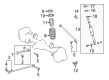
2001 Toyota Land Cruiser Coil Spring, Rear Driver Side
Part Number: 48231-6A690$253.84 MSRP: $362.42You Save: $108.58 (30%)Ships in 1-3 Business DaysProduct Specifications- Other Name: Spring, Coil, Rear; Coil Spring, Rear Left; Coil Spring Rear; Coil Springs; Spring; Spring, Coil, Rear Driver Side
- Manufacturer Note: H=504,GREEN & PINK PAINTED
- Position: Rear Driver Side
- Part Name Code: 48231B
- Item Weight: 18.00 Pounds
- Item Dimensions: 18.1 x 11.1 x 5.8 inches
- Condition: New
- Fitment Type: Direct Replacement
- SKU: 48231-6A690
- Warranty: This genuine part is guaranteed by Toyota's factory warranty.

2001 Toyota Land Cruiser Coil Spring, Rear Passenger Side
Part Number: 48231-6A680$247.90 MSRP: $353.95You Save: $106.05 (30%)Ships in 1-3 Business DaysProduct Specifications- Other Name: Spring, Coil, Rear; Coil Spring, Rear Right; Coil Springs; Spring; Spring, Coil, Rear Passenger Side
- Manufacturer Note: H=498,GREEN&GREEN PAINTED
- Position: Rear Passenger Side
- Part Name Code: 48231A
- Item Weight: 17.40 Pounds
- Item Dimensions: 17.9 x 11.7 x 5.7 inches
- Condition: New
- Fitment Type: Direct Replacement
- SKU: 48231-6A680
- Warranty: This genuine part is guaranteed by Toyota's factory warranty.
2001 Toyota Land Cruiser Coil Spring, Rear Driver Side
Part Number: 48231-6A670$199.25 MSRP: $284.48You Save: $85.23 (30%)Product Specifications- Other Name: Spring, Coil, Rear; Coil Spring, Rear Left; Coil Springs; Spring; Spring, Coil, Rear Driver Side
- Manufacturer Note: H=492,YELLOW&BROWN PAINTED
- Position: Rear Driver Side
- Part Name Code: 48231B
- Item Weight: 4.30 Pounds
- Item Dimensions: 17.9 x 10.7 x 5.8 inches
- Condition: New
- Fitment Type: Direct Replacement
- SKU: 48231-6A670
- Warranty: This genuine part is guaranteed by Toyota's factory warranty.
2001 Toyota Land Cruiser Coil Spring, Rear Passenger Side
Part Number: 48231-6A660$193.91 MSRP: $276.87You Save: $82.96 (30%)Product Specifications- Other Name: Spring, Coil, Rear; Coil Spring, Rear Right; Coil Springs; Spring; Spring, Coil, Rear Passenger Side
- Manufacturer Note: H=486;YELLOW & PURPLE PAINTED
- Position: Rear Passenger Side
- Part Name Code: 48231A
- Item Weight: 4.20 Pounds
- Item Dimensions: 17.9 x 11.2 x 5.9 inches
- Condition: New
- Fitment Type: Direct Replacement
- SKU: 48231-6A660
- Warranty: This genuine part is guaranteed by Toyota's factory warranty.
2001 Toyota Land Cruiser Coil Springs
Looking for affordable OEM 2001 Toyota Land Cruiser Coil Springs? Explore our comprehensive catalogue of genuine 2001 Toyota Land Cruiser Coil Springs. All our parts are covered by the manufacturer's warranty. Plus, our straightforward return policy and speedy delivery service ensure an unparalleled shopping experience. We look forward to your visit!
2001 Toyota Land Cruiser Coil Springs Parts Q&A
- Q: How to remove the coil springs on 2001 Toyota Land Cruiser?A: Begin coil spring removal by unscrewing both rear wheels until achieving a torque value of 131 Nm (1,340 kgf-cm, 97 ft-lbs). Support the rear axle housing with a jack while you disconnect the shock absorber by removing its bolt with 98 Nm torque before removing the nut and retainer hardware with 2 more retainers and shock absorber and cushion while holding the piston rod with 69 Nm torque. After unthreading the 2 retainers as well as the cushion from the shock absorber. First stabilize the suspension before securing the nut and bolt. Then disconnect the lateral control rod by removing its nut and washer, bolt, and torquing them at 150 Nm. Following a torque pattern of 18 Nm for LH and RH stabilizer bar bracket bolts. Begin lower positioning the axle housing with care because lowering too quickly may break both brake line and parking brake cable while simultaneously pulling off the insulator. Follow the spring from the frame when removing the bolt at a torque of 28 Nm (290 kgf-cm, 21 ft. lbs.). Assess the shock absorber rod function by first compressing it then extending it for evaluation of resistance or sound abnormalities before replacing the unit when detection of faults occurs. To safely discard the shock absorber users should drill a hole that measures between 2 and 3 millimeters (0.079 - 0.118 inches) for gas discharge purposes yet they should be cautious about potential chip release during this process because the gas substance is non-toxic colorless and odorless. Install the bushing using Special Service Tool: 09710-14013 (09710-00061), 09710-28012 (09710-07031), 09950-70010 (09951-07100) beneath a press that will follow the exact opposite sequence for installation.
Related 2001 Toyota Land Cruiser Parts
 2001 Toyota Land Cruiser Control Arm
 2001 Toyota Land Cruiser Axle Beam Mount
 2001 Toyota Land Cruiser Bump Stop
 2001 Toyota Land Cruiser Coil Spring Insulator
 2001 Toyota Land Cruiser Control Arm Bushing
 2001 Toyota Land Cruiser Front Cross-Member
 2001 Toyota Land Cruiser Steering Knuckle
 2001 Toyota Land Cruiser Strut Housing
 2001 Toyota Land Cruiser Sway Bar Bracket
 2001 Toyota Land Cruiser Sway Bar Bushing
 2001 Toyota Land Cruiser Sway Bar Kit
 2001 Toyota Land Cruiser Sway Bar Link