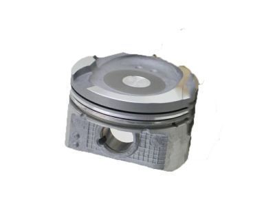
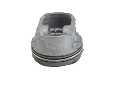
My Garage
Cart
Make sure this part fits

Toyota 13101-22032
Piston

2000-2006 Toyota 1310122032

Customer Questions & Expert Answers (3)
Toyota 13101-22032 Piston
  • Part Description
    Piston Sub-Assembly, With Pin
  • Part Name Code
    13101
  • Replaces
    13101-22031, 13101-22030
  • Manufacturer
    Toyota
Make sure this part fits
$97.16 MSRP: $136.37
You Save: $39.21 (29%)
Ships in 1-3 Business Days
1
ADD TO CART
  • Related Parts
  • Product Specifications
  • Vehicle Fitment
  • Customer Questions & Expert Answers
  • Product Specifications

    BrandGenuine Toyota
    Part Name Code13101
    Manufacturer Part Number13101-22032
    Part DescriptionPiston Sub-Assembly, With Pin
    Other NamesPiston Sub-Assembly, W/Pin
    Manufacturer NoteSTD
    Item Dimensions4.0 x 3.7 x 3.5 inches
    Item Weight1.20 Pounds
    ConditionNew
    Fitment TypeDirect Replacement
    Replaces13101-22031, 13101-22030
    Require Quantity4
    ManufacturerToyota
    SKU13101-22032
    WarrantyThis genuine Toyota part is guaranteed by Toyota's factory warranty.
    Shipping & ReturnShipping Policy Return Policy
    Warning: California's Proposition 65
  • Vehicle Fitment

    Year Make Model Trim Engine
    2000-2005 Toyota CelicaGT4 Cyl 1.8 L GAS
    2000-2005 Toyota MR2 SpyderBase4 Cyl 1.8 L GAS
    2003-2006 Toyota MatrixBase, XR4 Cyl 1.8 L GAS
  • Customer Questions & Expert Answers

    Q:
    Is 13101-22032 a good match for my car? Posted by ToyotaPartsNow Specialist
    A:
    Find out if part number 13101-22032 is the right fit for your car by Selecting Your Vehicle model.
    Posted by ToyotaPartsNow Specialist
    Q:
    How to disassemble the piston on Toyota MR2 Spyder? Posted by Customer
    A:
    The first step requires installing the engine to an engine stand followed by removing the cylinder head and water bypass pipe along with its nuts, bolts, pipe and gasket (2) and then followed by removing the thermostat and knock sensor, engine coolant drain union, oil pump, oil filter and oil filter union requiring a 12 mm hexagon wrench. The removal procedure begins with oil pan deinstallation requiring bolt disassembly of 14 units combined with two nuts and subsequent application of Special Service Tool: 09032-00100 to slice off sealant from the bearing cap subassembly to oil pan interface space while maintaining an undamaged state of both components. Use a dial indicator to check connecting rod thrust clearance before removing any components except for the connecting rod assembly(s). Keep the clearance value within 0.0063 to 0.0135 inch (0.160 to 0.342 mm). To inspect oil clearance with Plastigage measure 0.028 - 0.060 mm (0.0011 - 0.0024 inch) as standard range and maximum is 0.08 mm (0.0031 inch). Align the connecting rod caps based on their matchmarks. Push all assemblies through the cylinder block opening from the top while maintaining organizational order with bearings and components. The second step requires removing the bearing cap subassembly and crankshaft rear oil seal while performing an oil clearance check on main journals and bearings before replacing identified damaged components. A dial indicator should be used to measure thrust clearance on the crankshaft before replacing thrust washers if it falls outside the standard range of 0.04 - 0.24 mm (0.0016 - 0.0094 inch). To perform this task start by inspecting the piston and piston pin fit followed by deploying a piston ring expander to extract rings before disconnecting the connecting rod from the piston utilizing snap ring prying and heating the piston with subsequent tapping of the piston pin using plastic-faced hammer and brass bar and organizing all components correctly.
    Posted by ToyotaPartsNow Specialist
    Q:
    How should Piston be cleaned and assembled before installation on Toyota MR2 Spyder? Posted by Customer
    A:
    All installation components must undergo cleaning process followed by application of fresh engine oil on moving elements before assembly with new gaskets O-rings and oil seals. Begin by installing the piston and connecting rod while integrating a new snap ring at one end of the piston pin hole where the end gap must not face the pin hole cutout and heat the piston to 80 - 90 degrees Celsius (176 - 194 degrees Fahrenheit). Then apply engine oil on the piston pin, position the front marks correctly between the piston and connecting rod until you push the piston inside. You should place the second snap ring at the piston pin hole and arrange it away from the end gap-to-pin hole cutout alignment. Fit compression rings using a piston ring expander which will have the code mark in the upward position while avoiding ring end alignment. When installing connecting rod bearings users should position the claw of the bearing against the groove and then install the bearings. Begin with main bearings by inserting the claw of each bearing into the cylinder block claw grooves before inserting the five upper bearings with proper orientation that includes oil hole placement in the block followed by lower bearing installation in the main bearing cap. Two thrust washers need installation under the No. 3 journal position of the cylinder block with the oil grooves directed toward the outside. Install the crankshaft onto the cylinder block while placing the bearing cap subassembly on top. Remove FIPG material totally and thoroughly clean all components. Seal packing (Part No. 08826-00080 or equivalent) should be applied to the bearing cap subassembly before part assembly begins within 3 minutes and subassembly completion should include plastic-faced hammer tapping for proper fitting. The technician must apply paint to the bearing cap subassembly bolts to mark their front section prior to reducing torque from 44 Nm (449 kgf-cm, 32 ft. lbs.) to 22 Nm (225 kgf-cm, 16 ft. lbs.) in several passes while tightening them for installation. The technician should ensure each bolt opens to a 45 degrees angle then verifies the painted marks align at a 90 degrees angle to the front section. The installation procedure for hexagon head bearing cap subassembly bolts requires a 18.5 Nm (189 kgf-cm, 14 ft. lbs.) torque setting followed by a smooth crankshaft rotation test. Use a piston ring compressor to install the piston assemblies by putting their front mark in the forward direction before confirming the thrust clearance of the crankshaft. The installation of the connecting rod cap requires placing it onto the rod by matching its numbered cap with the rod and positioning the pin dowels while checking that the protruding cap oriented right. Install and alternately tighten the 2 connecting rod cap bolts to 20 Nm (204 kgf-cm, 15 ft. lbs.), use paint to mark the front bolting positions before readjusting them by 90 degrees for smooth crankshaft rotation. Before finishing check that thrust clearance on connecting rods is correct then install the rear crankshaft oil seal followed by a new gasket with oil strainer that needs two nuts and a bolt tightened to 9 Nm (92 kgf-cm, 80 inch lbs.). The technician should remove all FIPG packing materials from the oil pan before using a nozzle to apply new seal packing (Part No. 08826-00080 or equivalent) with a 4 to 5 mm (0.16 to 0.20 inch) diameter opening. Then install the oil pan with 14 bolts and 2 nuts by tightening them evenly to 9 Nm (92 kgf-cm, 80 inch lbs.). Begin with installing an oil filter union to 30 Nm (306 kgf-cm, 21 ft. lbs.) while also wrapping oil filter, oil pump, and engine coolant drain union joints with adhesive (Part No. 08833-00080, THREE BOND 1344, LOCTITE 242 or equivalent) to 20 Nm (204 kgf-cm, 15 ft. lbs.). Rotate the drain union clockwise to position the drain port facing downwards. The knock sensor installation requires 39 Nm (400 kgf-cm, 29 ft. lbs.) torque and the thermostat should follow, after that the water bypass pipe gets secured at 9 Nm (92 kgf-cm, 80 inch lbs.) and finally the installation process includes the timing sprockets with timing chain and the engine stand removal.
    Posted by ToyotaPartsNow Specialist
    If you have any questions about this product, please don't hesitate to ask us. We will be happy to help you!

OEM Toyota 13101-22032, Excellent Performance and Perfect Fitment

To ensure reliability, purchase Toyota part # 13101-22032 Piston. It is sometimes referred to as Toyota Piston. OEM parts are unrivaled in terms of quality. They go through extensive quality control inspections and are produced in accordance with Toyota's official factory specifications. All of these remove defects and imperfections. So you can relax knowing they promise exceptional lifespan and flawless fitment.

ToyotaPartsNow.com is a leading supplier of genuine Toyota parts such as Toyota 1310122032 Piston. At ToyotaPartsNow.com, we have a wide variety of OEM Toyota parts available at competitive prices. Our comprehensive range of genuine Toyota parts come with a manufacturer's warranty for peace of mind. We also prioritize customer satisfaction, providing a hassle-free return policy and expedited delivery for all our parts. For detailed Toyota parts information, click here.
Choose ToyotaPartsNow for discounted prices, exceptional service and fast delivery