×
ToyotaParts- Hello
- Login or Register
- Quick Links
- Live Chat
- Track Order
- Parts Availability
- RMA
- Help Center
- Contact Us
- Shop for
- Toyota Parts
- Scion Parts
My Garage
My Account
Cart
OEM Toyota Solara Neutral Safety Switch
Transmission Range Sensor- Select Vehicle by Model
- Select Vehicle by VIN
Select Vehicle by Model
orMake
Model
Year
Select Vehicle by VIN
For the most accurate results, select vehicle by your VIN (Vehicle Identification Number).
3 Neutral Safety Switchs found


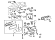
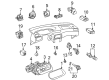
Toyota Solara Neutral Safety Switch Part Number: 84540-20200
$168.01 MSRP: $237.84You Save: $69.83 (30%)Ships in 1-2 Business Days

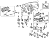
Toyota Solara Neutral Safety Switch Part Number: 84540-0E010
$148.86 MSRP: $210.73You Save: $61.87 (30%)Ships in 1 Business Day
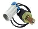
Toyota Solara Neutral Safety Switch Part Number: 84520-33010
$64.33 MSRP: $90.30You Save: $25.97 (29%)Ships in 1-3 Business Days
Toyota Solara Neutral Safety Switch
Choose genuine Neutral Safety Switch that pass strict quality control tests. You can trust the top quality and lasting durability. Shopping for OEM Neutral Safety Switch for your Toyota Solara? Our website is your one-stop destination. We stock an extensive selection of genuine Toyota Solara parts. The price is affordable so you can save more. It only takes minutes to browse and find the exact fit. Easily add to cart and check out fast. Our hassle-free return policy will keep you stress-free. We process orders quickly for swift delivery. Your parts will arrive faster, so you can get back on the road sooner.
Toyota Solara Neutral Safety Switch Parts and Q&A
- Q: How to service and repair the park/neutral safety switch on Toyota Solara?A:A proper repair of the park/neutral position switch requires starting with removal of the battery and successive removal of the engine cover No. 1 sub-assembly, air cleaner assembly and air cleaner hose No. 1 and intake air resonator sub-assembly and engine under cover LH. The floor Shift Cable transmission control shift can be detached through these steps: Unconnect the park/neutral position switch connector then remove the control shaft lever nut and disconnect the control cable from the lever and remove its bracket clip. First disconnect the park/neutral position switch assembly by removing its bolts and then successively take off the lock plate, lock nut and control shaft lever. The switch must be pulled out after you remove the washers and nut and pry up the lock plate. In this step check the park/neutral position switch assembly which requires you to apply the parking brake, turn on the Ignition Switch to ON position, press the brake pedal deeply and confirm engine start-up functions properly in N or P mode but Back Up light and reverse warning buzzer activates only in R position; perform continuity test when a failure occurs. Implement the adjustment of the park/neutral position switch assembly through the following steps: loosen the 2 bolts, position the shift lever to N, align the groove with the neutral basic line while holding the switch in position before tightening the bolts to 5.4 Nm (55 kgf-cm, 48 inch lbs.) and complete the inspection. Place all installation materials first then attach the park/neutral position switch on the manual valve shaft and set the 2 bolts before putting in a new lock plate and tightening the nut to 6.9 Nm (70 kgf-cm, 61 inch lbs). The installation procedure requires the control shaft lever to be placed temporarily before turning it counterclockwise until it stops and continuing clockwise to the second notch. After removing the lever the operator must replace it with the groove aligned to the neutral basic line while tightening the two bolts to 5.4 Nm (55 kgf-cm, 48 inch lbs.) before using a screwdriver to stake the nut in position with the lock plate. The final stage involves adding the washer and nut with 13 Nm (130 kgf-cm, 9 ft. lbs.) torque. The next step involves connecting the park/neutral position switch cable before connecting the floor shift cable transmission control shift through leveraging the control cable to the control shaft lever with the nut fastened at 15 Nm (153 kgf-cm, 11 ft. lbs.) tension followed by installing a new clip on the bracket. The last installation step involves putting back the engine under cover LH and intake air resonator sub-assembly and air cleaner hose No. 1 and air cleaner assembly and engine cover No. 1 sub-assembly and battery with followup checks on the shift lever position and park/neutral position switch assembly and an initialization procedure.
- Q: How to replace the Park/Neutral Safety Switch Assy (ATM) on Toyota Solara?A:The replacement of the park/neutral position switch assy (ATM) begins with removal of essential components such as battery followed by engine cover sub-assy No.1, air cleaner assy, air cleaner hose No.1, intake air resonator sub-assy, and finally engine under cover LH. Disconnection of the floor Shift Cable transmission control shift happens by removing the nut from the control shaft lever, disconnecting the control cable from the control shaft lever and park/neutral position switch connector and by removing the clip from the control cable bracket. Begin the park/neutral position switch assy removal procedure by uninstalling the nut, washer and control shaft lever. Then pry up the lock plate, remove the lock nut and lock plate before pulling out the switch when all 2 bolts are removed. When installing the new park/neutral position switch assy begin by connecting it to the manual valve shaft then fasten the 2 bolts even if just temporary before placing a new lock plate and tightening the nut to reach 6.9 Nm (70 kgf-cm, 61 inch lbs.). The temporary installation of the control shaft lever should begin with a counterclockwise rotation until it reaches its stopping point followed by clockwise movement of 2 notches before the lever removal. Place the switch into position so its groove matches the neutral basic line while securing the 2 bolts to 5.4 Nm (55 kgf-cm, 48 inch lbs.). Install the control shaft lever after placing the washer on top followed by the nut and attain a torque reading of 13 Nm (130 kgf-cm, 9 ft. lbs.). Connect the park/neutral position switch connector followed by attaching the control cable to the control shaft lever along with the necessary nut that should be tightened to achieve 15 Nm (153 kgf-cm, 11 ft. lbs.) torque. The control cable also needs a new clip to attach to the bracket. Engine under cover LH and intake air resonator sub-assy replacement must be combined with the installation of air cleaner hose No.1 and air cleaner assy and engine cover sub-assy No.1 and battery before completing the process by adjusting shift lever position and inspecting the park/neutral position switch assy along with initialization steps.


Related Toyota Solara Parts
 Toyota Solara Back Up Light Switch
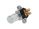 Toyota Solara Dimmer Switch
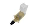 Toyota Solara Door Jamb Switch
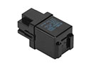 Toyota Solara Flasher Relay
 Toyota Solara Hazard Warning Switch
 Toyota Solara Ignition Lock Cylinder
 Toyota Solara Ignition Switch
 Toyota Solara Speedometer
 Toyota Solara TPMS Sensor
 Toyota Solara Turn Signal Flasher
 Toyota Solara Turn Signal Relay
 Toyota Solara Turn Signal Switch