×
ToyotaParts- Hello
- Login or Register
- Quick Links
- Live Chat
- Track Order
- Parts Availability
- RMA
- Help Center
- Contact Us
- Shop for
- Toyota Parts
- Scion Parts
My Garage
My Account
Cart
OEM Toyota Camry Clutch Disc
Friction Disc- Select Vehicle by Model
- Select Vehicle by VIN
Select Vehicle by Model
orMake
Model
Year
Select Vehicle by VIN
For the most accurate results, select vehicle by your VIN (Vehicle Identification Number).
8 Clutch Discs found


Toyota Camry Disc Part Number: 31250-20253
$122.54 MSRP: $173.47You Save: $50.93 (30%)Ships in 1-3 Business Days

Toyota Camry Disc Part Number: 31250-33061
$216.79 MSRP: $309.53You Save: $92.74 (30%)Ships in 1-3 Business Days
Toyota Camry Disc Part Number: 31250-33042
$119.72 MSRP: $169.48You Save: $49.76 (30%)Ships in 1-3 Business Days
Toyota Camry Disc Part Number: 31250-32052
$124.22 MSRP: $175.86You Save: $51.64 (30%)Ships in 1-3 Business Days
Toyota Camry Disc Part Number: 31250-33051
$136.76 MSRP: $193.60You Save: $56.84 (30%)Ships in 1-3 Business Days
Toyota Camry Disc Part Number: 31250-17040-84
$55.81 MSRP: $77.84You Save: $22.03 (29%)Ships in 1-3 Business Days
Toyota Camry Disc Part Number: 31250-33032
$117.18 MSRP: $164.48You Save: $47.30 (29%)Ships in 1-3 Business Days

Toyota Camry Disc Part Number: 31250-20140-84
$61.93 MSRP: $87.11You Save: $25.18 (29%)
Toyota Camry Clutch Disc
Choose genuine Clutch Disc that pass strict quality control tests. You can trust the top quality and lasting durability. Shopping for OEM Clutch Disc for your Toyota Camry? Our website is your one-stop destination. We stock an extensive selection of genuine Toyota Camry parts. The price is affordable so you can save more. It only takes minutes to browse and find the exact fit. Easily add to cart and check out fast. Our hassle-free return policy will keep you stress-free. We process orders quickly for swift delivery. Your parts will arrive faster, so you can get back on the road sooner.
Toyota Camry Clutch Disc Parts and Q&A
- Q: How to overhaul the clutch disc on Toyota Camry?A:The overhaul process for the clutch disc starts with manual transaxle assembly removal followed by disassembly of the clutch release fork boot, clutch release bearing assembly, clutch release fork sub-assembly and release bearing hub clip and release fork support. Start by matching marks on the clutch cover assembly to the flywheel sub-assembly. After that loosen set bolts by one turn at a time to release spring tension before removing set bolts and pulling off the clutch cover assembly while avoiding dropping the clutch disc assembly. The clutch disc assembly needs removal after which maintain the lining part as well as Pressure Plate and surface of the flywheel sub-assembly completely free from oil and foreign attachments. The clutch disc assembly needs inspection with vernier calipers to check rivet head depth against a maximum of 0.3 mm (0.012 inch). If the depth exceeds this threshold, the clutch disc assembly requires replacement. Place the clutch disc assembly into the transaxle assembly with proper installation direction and check its runout with the dial indicator because excessive 0.8 mm (0.031 inch) runout requires replacement. A traditional caliper measurement must be performed to evaluate clutch cover assembly diaphragm spring wear. The measurement depth should be below 0.5 mm (0.020 inch) and the width should be under 6.0 mm (0.236 inch); replacement is needed when either measurement exceeds these limits. A dial indicator should be used to check flywheel sub-assembly runout which must stay below 0.1 mm (0.004 inch) or require replacement. A hand operation of the clutch release bearing assembly needs axial force checks before replacement if required. Install the clutch disc assembly by inserting Special Service Tool: 09301-00220 so it fits into both the clutch disc assembly and the flywheel sub-assembly in the correct direction. Reinstall the clutch cover assembly after securing the six bolts to a torque of 19.1 Nm (199 kgf-cm, 14 ft. lbs.) while matching all the bolts' points and verifying the disc remains directly in the clutch center. The procedure to check and adjust clutch cover assembly requires the use of Special Service Tool: 09333-00013 for diaphragm spring tip alignment inspection with a dial indicator to confirm maximum non-alignment stays under 0.5 mm (0.020 inch). Those working on the installation should install the manual transaxle release fork support by applying 47.1 Nm (480 kgf-cm, 35 ft. lbs.) torque and then connect the release bearing hub clip to the assembly. Apply Part No. 08887-01806 release hub grease or equivalent to points where the release fork contacts the release bearing assembly before installing the release fork to the bearing assembly. The input shaft requires clutch spline grease (Part No. 08887-01706, clutch spline grease or equivalent) before installing the release fork with release bearing assembly to the manual transaxle assembly. Make sure the release bearing moves without resistance after installation. At the conclusion of assembly you must add the clutch release fork boot and manual transaxle assembly.

Related Toyota Camry Parts
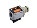 Toyota Camry Shift Solenoid
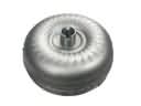 Toyota Camry Torque Converter
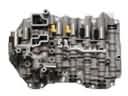 Toyota Camry Valve Body
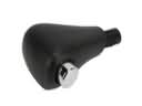 Toyota Camry Automatic Transmission Shift Levers
 Toyota Camry Clutch Fork
 Toyota Camry Clutch Release Bearing
 Toyota Camry Clutch Slave Cylinder
 Toyota Camry Clutch Slave Repair Kit
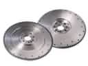 Toyota Camry Flywheel
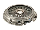 Toyota Camry Pressure Plate
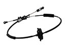 Toyota Camry Shift Cable
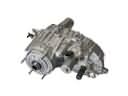 Toyota Camry Transfer Case