×
ToyotaParts- Hello
- Login or Register
- Quick Links
- Live Chat
- Track Order
- Parts Availability
- RMA
- Help Center
- Contact Us
- Shop for
- Toyota Parts
- Scion Parts
My Garage
My Account
Cart
OEM Toyota Camry A/C Compressor Clutch
Air Conditioning Clutch- Select Vehicle by Model
- Select Vehicle by VIN
Select Vehicle by Model
orMake
Model
Year
Select Vehicle by VIN
For the most accurate results, select vehicle by your VIN (Vehicle Identification Number).
46 A/C Compressor Clutches found
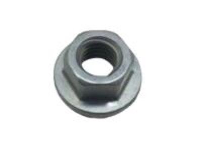
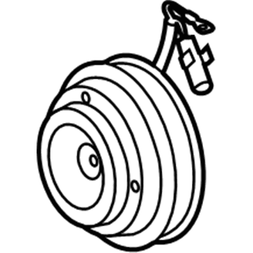
Toyota Camry Hub Sub-Assembly, Magnet Clutch Part Number: 88403-32010
$135.11 MSRP: $191.26You Save: $56.15 (30%)Ships in 1-3 Business Days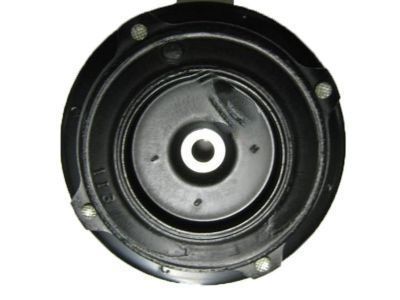
Toyota Camry Clutch Assembly Part Number: 88410-33150
$175.90 MSRP: $251.15You Save: $75.25 (30%)Ships in 1-3 Business Days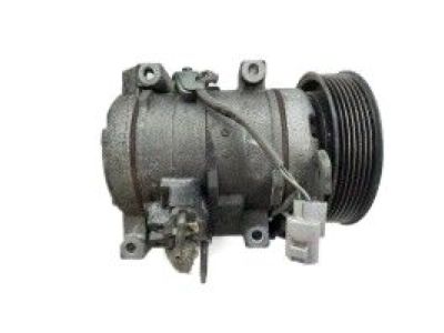
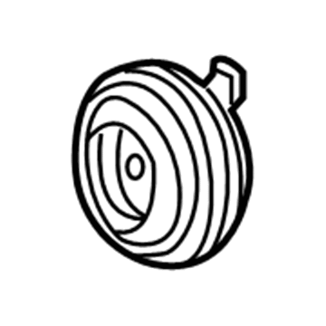
Toyota Camry Clutch & Pulley Part Number: 88410-42080
$231.01 MSRP: $329.83You Save: $98.82 (30%)Ships in 1-3 Business Days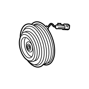
Toyota Camry Clutch Assembly, Magnet Part Number: 88410-0N010
$156.26 MSRP: $221.21You Save: $64.95 (30%)Ships in 1-3 Business Days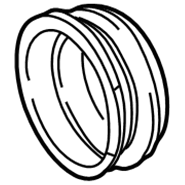
Toyota Camry Pulley Part Number: 88412-33040
$347.49 MSRP: $509.25You Save: $161.76 (32%)Ships in 1-3 Business Days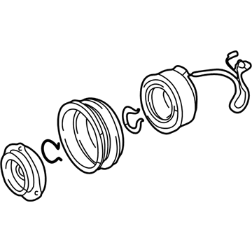
Toyota Camry Clutch & Pulley Part Number: 88410-33110
$661.13 MSRP: $968.89You Save: $307.76 (32%)Ships in 1-3 Business Days
Toyota Camry Clutch Part Number: 88410-33020
$123.38 MSRP: $175.00You Save: $51.62 (30%)Ships in 1-3 Business Days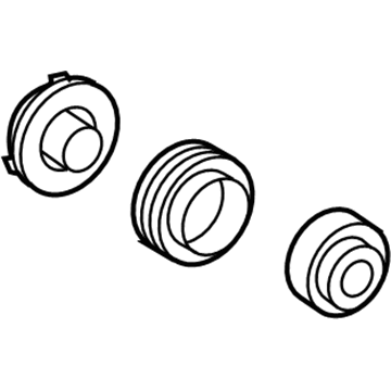
Toyota Camry Clutch & Pulley Part Number: 88410-07020
$131.59 MSRP: $186.28You Save: $54.69 (30%)Ships in 1-3 Business Days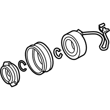
Toyota Camry Clutch Part Number: 88410-06070
$129.24 MSRP: $182.95You Save: $53.71 (30%)Ships in 1-3 Business Days
Toyota Camry Clutch Assembly, Magnet Part Number: 88410-33040
$140.99 MSRP: $199.59You Save: $58.60 (30%)Ships in 1-3 Business Days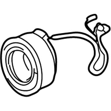
Toyota Camry Clutch Coil Part Number: 88411-33050
$143.06 MSRP: $202.51You Save: $59.45 (30%)Ships in 1-3 Business Days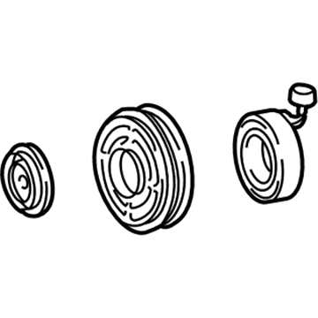
Toyota Camry Clutch & Pulley Part Number: 88410-42040
$186.62 MSRP: $266.45You Save: $79.83 (30%)Ships in 1-2 Business DaysToyota Camry Clutch Assembly, Magnet Part Number: 88410-33120
$249.30 MSRP: $355.94You Save: $106.64 (30%)Ships in 1-3 Business Days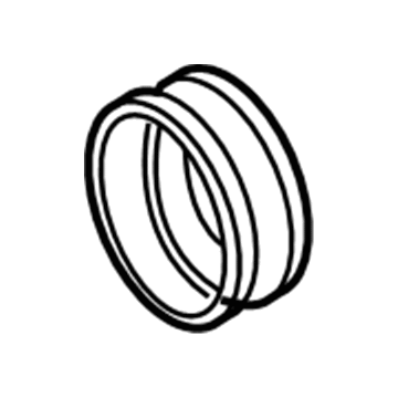
Toyota Camry Pulley Part Number: 88412-06040
$267.94 MSRP: $382.56You Save: $114.62 (30%)Ships in 1-3 Business Days
Toyota Camry Pulley Part Number: 88412-07020
$285.08 MSRP: $407.02You Save: $121.94 (30%)Ships in 1-3 Business DaysToyota Camry Clutch Part Number: 88412-33010
$302.47 MSRP: $431.86You Save: $129.39 (30%)Ships in 1-3 Business Days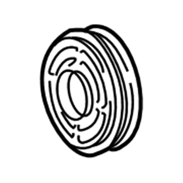
Toyota Camry Pulley Part Number: 88412-42010
$327.99 MSRP: $468.29You Save: $140.30 (30%)Ships in 1-3 Business DaysToyota Camry Clutch & Pulley Part Number: 88410-06090
$69.90 MSRP: $98.13You Save: $28.23 (29%)Ships in 1-3 Business Days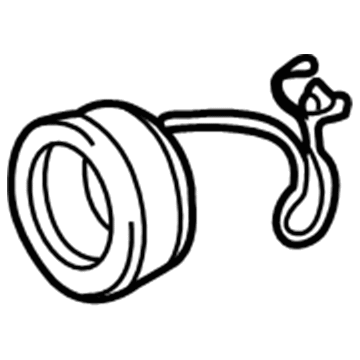
Toyota Camry Clutch Coil Part Number: 88411-33030
$107.21 MSRP: $150.49You Save: $43.28 (29%)Ships in 1-3 Business DaysToyota Camry Clutch & Pulley Part Number: 88410-06100
| Page 1 of 3 |Next >
1-20 of 46 Results
Toyota Camry A/C Compressor Clutch
Choose genuine A/C Compressor Clutch that pass strict quality control tests. You can trust the top quality and lasting durability. Shopping for OEM A/C Compressor Clutch for your Toyota Camry? Our website is your one-stop destination. We stock an extensive selection of genuine Toyota Camry parts. The price is affordable so you can save more. It only takes minutes to browse and find the exact fit. Easily add to cart and check out fast. Our hassle-free return policy will keep you stress-free. We process orders quickly for swift delivery. Your parts will arrive faster, so you can get back on the road sooner.
The air-conditioning compressor of the Toyota Camry is engaged by the A/C Compressor Clutch to provide cool air. Serve as a support for the compressor, a belt pulley turns while the engine runs. The Toyota Camry systems is made to fit the device. When the driver activates A/C, the wire coil inside the unit becomes an electromagnet that grabs the clutch hub tightly against the rotating pulley. While the air conditioning system is engaged, the A/C Compressor Clutch transmits engine power into the compressor shaft. The compressor then forces refrigerant towards the evaporator and a suction and discharge occurs enabling cooling. When the compressor is turned off, the compressor clutch is disconnected and the pulley will rotate freely without powering the compressor. In this way, the unnecessary engine load is avoided. The A/C Compressor Clutch may slip or even fail to engage in case it is worn. When the A/C Compressor Clutch fails or slips it may be due to wear on the compressor that is as a result of heat, friction or cycling. Toyota Camry A/C Compressor Clutch is a reliable part of the device that keeps the air-conditioning parts functioning in harmony and ensures the comfort of the Camry interior.
Toyota Camry A/C Compressor Clutch Parts and Q&A
- Q:How to service and repair the A/C Compressor Clutch on Toyota Camry?A:Service and repair of the compressor clutch follow these steps: let the engine reach idle speed with A/C turned on for ten minutes before engine shutdown and battery terminal cable detaching. Eliminate refrigerant from the refrigeration system before proceeding to remove the Drive Belt. When working on 1MZ-FE engines begin by removing the suction hose through bolt removal from its clamp then disconnect the wire harness clamp and unscrewing all nut and bolt components. Immediately place caps over open system fittings in order to block out moisture and dirt intrusion. Proceed with disconnecting the discharge hose after you remove its bolt and apply caps to the exposed fittings. You should start by disconnecting the generator connector followed by taking out the nut and wire before disconnecting the wire harness from its clip and taking out the pivot bolt and plate washer along with the adjusting lock bolt. Connect 5S-FE engine models by detaching suction and discharge hoses through the removal of two bolts followed by fitting caps to the ends. Detach the compressor by disconnecting the connector while removing its three bolts. Engine 1MZ-FE requires users to disconnect the connector before removing two bolts and a nut with the drive belt adjusting bar bracket followed by taking out the compressor through three bolt removal. The installation of the compressor for 5S-FE engine models necessitates bolt installation at three locations with the torque set to 25 N.m (250 kgf.cm, 18 ft.lbf) and connector attachment afterwards. To install the compressor on 1MZ-FE engines position the three bolts with equal torque while next installing the drive belt adjusting bar bracket through two bolts and a nut which needs tightening to 25 N.m (250 kgf.cm, 18 ft.lbf) for Bolt (A), 18 N.m (185 kgf.cm, 13 ft.lbf) for bolt (B) and 25 N.m (250 kgf.cm, 18 ft.lbf) for the nut before connecting the connector. Attach 2 bolts on the discharge and suction hoses of 5S-FE engine models while torquing them to 10 N.m (100 kgf.cm, 7 ft.lbf). Before hose installation, apply compressor oil to two new O-rings. On 1MZ-FE engine models position the generator on its bracket using the pivot bolt and adjusting lock bolt but maintain them loose before connecting both the generator connector and generator wire with its nut. The compressed air hose requires installation using a bolt securing it with 10 N.m (100 kgf.cm, 7 ft.lbf) torque strength during which compressing oil should be used to lubricate the new O-ring before assembly. The procedure begins with plumbing and tightening the suction hose join by screwing the bolt and nut to 32 N.m (330 kgf.cm, 24 ft.lbf) values at the piping intersection then continuing with suction hose clamping bolt installation and wire harness clamp attachment. Install the drive belt next then restore the negative terminal cable connection before evacuating air from the system and charging it with 800 plus or minus 50 g (28.22 plus or minus 1.76 oz.) of refrigerant. A gas detector should be used to check for leaks while technicians should refasten loose joints with their specified torque settings. When leaks are identified the system should undergo an A/C operation check together with additional testing for leakage.
Related Toyota Camry Parts
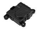 Toyota Camry Blend Door Actuator
 Toyota Camry A/C Condenser
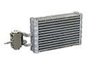 Toyota Camry Evaporator
 Toyota Camry Heater Core
 Toyota Camry A/C Accumulator
 Toyota Camry A/C Compressor Cut-Out Switches
 Toyota Camry A/C Hose
 Toyota Camry A/C Service Cap
 Toyota Camry A/C Switch
 Toyota Camry A/C System Valve Core
 Toyota Camry Ambient Temperature Sensor
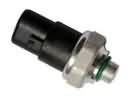 Toyota Camry HVAC Pressure Switch