×
ToyotaParts- Hello
- Login or Register
- Quick Links
- Live Chat
- Track Order
- Parts Availability
- RMA
- Help Center
- Contact Us
- Shop for
- Toyota Parts
- Scion Parts
My Garage
My Account
Cart
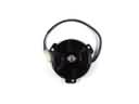
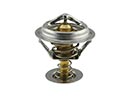
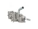
OEM Scion xD Water Pump
H2O Pump- Select Vehicle by Model
- Select Vehicle by VIN
Select Vehicle by Model
orMake
Model
Year
Select Vehicle by VIN
For the most accurate results, select vehicle by your VIN (Vehicle Identification Number).
2 Water Pumps found


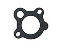
Scion xD Water Pump Part Number: 16100-39466
$100.00 MSRP: $140.37You Save: $40.37 (29%)Ships in 1-3 Business Days

Scion xD Water Pump Part Number: 16100-39465
$86.02 MSRP: $120.99You Save: $34.97 (29%)
Scion xD Water Pump
Choose genuine Water Pump that pass strict quality control tests. You can trust the top quality and lasting durability. Shopping for OEM Water Pump for your Scion xD? Our website is your one-stop destination. We stock an extensive selection of genuine Scion xD parts. The price is affordable so you can save more. It only takes minutes to browse and find the exact fit. Easily add to cart and check out fast. Our hassle-free return policy will keep you stress-free. We process orders quickly for swift delivery. Your parts will arrive faster, so you can get back on the road sooner.
Water Pump remains one of the most reliable and efficient parts required in fixing cars under this company's model, having the responsibility of regulating the engine temperature in Scion xD models. This essential part pumps a coolant through the water jackets surrounding the engine and picks up heat from the combustion being in the process of burning fuel, and then disperses the heat by passing through the radiator. Water Pump is an efficiency engaging element that also has the responsibility of maintaining the safety and correct working temperature of the engine with a view of avoiding such instances like overheating of the vehicle's engine and consequential damages to the same. Depending on the choice of the material used for cast iron or the lightweight aluminum design for Scion xD, the Water Pump has a long-life feature and an enhanced performance particularly in fast-moving cars that require an increased rate of coolant circulation. However, there are key features which are major strengths of Scion xD including electric water pumps which offer the following benefits;Less parasitic loss Independent flow control depending on the engine's temperature in the automotive market. The source for Water Pump comes in many types to ensure that drivers using any model configurations of the car can rely on the water pump's performance. In conclusion, the Water Pump demonstrates the company's high standard and progressive thinking as the component of the Scion xD's mechanics that keeps drivers happy on the road.
Scion xD Water Pump Parts and Q&A
- Q: How to remove the water pump assembly on Scion xD?A:Begin water pump assembly removal by first discharging fuel system pressure and then follow a sequence of removing the battery together with its tray and front wheels and engine under covers from both sides of the vehicle along with draining engine coolant. Start by removing the front wiper arm head caps followed by taking out the front wiper arm assemblies with blades (LH and RH) and the hood to cowl top seal and finally the cowl top ventilator louver sub-assembly together with its left louver. The removal process includes taking out the front Wiper Motor and link followed by the front air shutter seal (RH), outer cowl top panel, air cleaner assembly with bracket and battery carrier. The mechanic should remove the No. 2 cylinder head cover then take off the fan & generator V belt and No. 2 Radiator hose together with No. 1 radiator hose disconnection. Detach the No. 1 oil cooler outlet hose and No. 2 oil cooler inlet hose before taking out the hood lock assembly and both the No. 1 cooler cover and upper radiator support absorber followed by the upper radiator support sub-assembly. Separate the radiator assembly followed by the separation of pulley compressor assembly and the transmission control cable assembly (which is applicable for both automatic and manual transaxles). You need to disconnect the union to check valve hose alongside the No. 1 fuel vapor feed hose and remove the engine wire and heater water hose outlet A together with inlet A and fuel tube sub-assembly. To access the manual transaxle clutch release cylinder assembly professionals must first separate the clutch release cylinder assembly followed by the removal of the column hole cover silencer sheet then separate the steering sliding yoke sub-assembly along with the No. 1 steering column hole cover sub-assembly. For manual transaxles remove the shift lever knob sub-assembly together with console panel upper, console box cover rear, console box carpet, rear console box sub-assembly, front console box, front floor brace center, front Exhaust Pipe assembly and the front Axle Shaft nuts (LH and RH). The service technicians should execute the separation of Speed Sensors (front LH and RH) tie rod end sub-assemblies (LH and RH) front stabilizer link assemblies (LH and RH) and front lower suspension arm sub-assemblies (LH and RH). The first step includes disconnecting both front axle assemblies (LH and RH). The procedure ends with the removal of the engine assembly with transaxle and front suspension crossmember sub-assembly. Removal of the water pump assembly requires detachment of its five bolts together with the timing chain cover gasket.
- Q: How to install the water pump assembly on Scion xD?A:Begin the 2ZR-FE water pump assembly installation by applying a new water pump gasket to the timing chain cover after cleaning both surfaces. The water pump assembly needs 5 bolt attachments that require bolt A to reach 26 Nm (260 kgf-cm, 19 ft-lbf) while bolt B requires 24 Nm (240 kgf-cm, 17 ft-lbf). Follow the front suspension crossmember sub-assembly installation by fitting the engine assembly with transaxle. Move forward with front axle assembly installation for both left and right sides because the steps are identical between them. Repeat the previous installation process for front lower suspension arm sub-assemblies of both sides together with front stabilizer link assemblies and tie rod end sub-assemblies while stressing that these steps apply identically for both sides. The installation order includes the front Speed Sensors and front Axle Shaft nuts followed by front Exhaust Pipe assembly and front floor brace center before completing with front console box and rear console box assembly and console box carpet installation. Next install the console box cover rear and console panel upper and shift lever knob sub-assembly (for manual transaxle), No. 1 steering column hole cover sub-assembly, steering sliding yoke sub-assembly with column hole cover silencer sheet and clutch release cylinder assembly (for manual transaxle). Install these components: fuel tube sub-assembly and both heater water hose inlet and outlet A together with the engine wire, No. 1 fuel vapor feed hose and union to check valve hose and transmission control cables (automatic and manual transaxles). The installation process includes the pulley compressor assembly and Radiator assembly followed by the upper radiator support sub-assembly with upper radiator support absorber, No. 1 cooler cover, hood lock assembly, No. 2 oil cooler inlet hose for automatic transaxle and No. 1 oil cooler outlet hose for automatic transaxle and finishing with the front bumper cover, No. 1 radiator hose, No. 2 radiator hose, fan & generator V belt and appropriate adjustments and inspections of the fan & generator V belt. When assembling the engine reinstall the No. 2 cylinder head cover together with the battery holder and air cleaner bracket and air cleaner unit before adding the outer cowl top panel and front air shutter seal on the right-hand side and the front Wiper Motor linkage and moveable cowl ventilator louver to the left with its supporting sub-assembly unit before installing the hood to cowl top joint and main front wiper components including blades and left-hand head caps. At the end of installation please install the battery tray together with the battery then add engine coolant before checking for leakage of fuel exhaust air and engine oil. Finish by installing both engine undercovers and front wheels covers. Complete the procedure by verifying ignition timing then measuring engine idling speed and CO/HC levels while inspecting front wheel alignment and testing the VSC sensor signal.