×
ToyotaParts- Hello
- Login or Register
- Quick Links
- Live Chat
- Track Order
- Parts Availability
- RMA
- Help Center
- Contact Us
- Shop for
- Toyota Parts
- Scion Parts
My Garage
My Account
Cart
OEM Scion xB Shock Absorber
Suspension Shock Absorber- Select Vehicle by Model
- Select Vehicle by VIN
Select Vehicle by Model
orMake
Model
Year
Select Vehicle by VIN
For the most accurate results, select vehicle by your VIN (Vehicle Identification Number).
3 Shock Absorbers found


Scion xB Shock Absorber Part Number: 48530-59815
$60.19 MSRP: $84.48You Save: $24.29 (29%)Ships in 1-3 Business Days

Scion xB Shock Absorber Part Number: 48530-80420
$64.45 MSRP: $90.47You Save: $26.02 (29%)Ships in 1 Business Day

Scion xB Strut, Front Driver Side Part Number: 48520-80127
$121.01 MSRP: $171.31You Save: $50.30 (30%)Ships in 1-3 Business Days
Scion xB Shock Absorber
Choose genuine Shock Absorber that pass strict quality control tests. You can trust the top quality and lasting durability. Shopping for OEM Shock Absorber for your Scion xB? Our website is your one-stop destination. We stock an extensive selection of genuine Scion xB parts. The price is affordable so you can save more. It only takes minutes to browse and find the exact fit. Easily add to cart and check out fast. Our hassle-free return policy will keep you stress-free. We process orders quickly for swift delivery. Your parts will arrive faster, so you can get back on the road sooner.
A Shock Absorber is a valuable component of the suspension system and considerably famous for its durability and collectiveness, which might vary depending on the type of Scion xB model. Meant for controlling and minimizing shock impulses, the Scion xB Shock Absorber maintains the quality of the ride and the manner through which the car navigates roads by transforming kinetic energy into heat to control the vibrations and reduce the large movements of the suspension mechanism. In the xB, Scion has used twin tube and mono tube kinds, with twin tube simple in design and using gas to prevent the shock's body wearing out while mono tube better at releasing heat and achieving better performance. Among such options Position Sensitive Damping (PSD) and Acceleration Sensitive Damping (ASD) take the idea even further by changing how the Scion xB responds to the road, always keeping it smooth and comfortable. In addition to the improvement of the mechanical factor, the Scion xB Shock Absorber is also important to propel the efficiency and safety, as it determines the vehicle control when driving in different conditions. Known for compatibility with various xB generations in the market of automotive products, Scion xB Shock Absorber offers such modern technologies as electrorheological and magnetorheological dampers that can adjust the stiffness depending on the current speed. In conclusion, the Scion xB Shock Absorber is another of the renowned Scion car parts which prove that Scion is a company that pays a great deal of attention to product quality, thus, the Shock Absorber is a vital aspect of the xB performance and durability.
Scion xB Shock Absorber Parts and Q&A
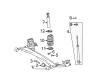
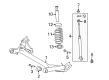
- Q: How to remove the rear shock absorber on Scion xB?A:To start the removal process of the rear shock absorber you should first remove the rear wheels and rear floor service hole cover. The support procedure starts by adding a jack and wooden block to the rear axle beam spring seat but avoids over-jacking and positions the rear shock absorber for compression between 20 to 30 mm (0.78 to 1.18 in.). The socket hexagon wrench with size 6 mm allows users to maintain the rear shock absorber rod before disconnecting the lock nut and rear shock absorber cushion retainer. Start by removing the rear suspension support after which you can safely remove the rear shock absorber assembly by unfastening the bolt under maintenance of the nut. Complete the process by taking away the rear No. 1 spring bumper.
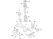
- Q: How to install the front shock absorber on Scion xB?A:You need to place the front shock absorber in a vise by installing a bolt and nut first in order to startInstallation. Place the front coil spring lower insulator while verifying the positioning pin enters the hole located inside the front shock absorber. Insert the front spring bumper after compressing the front coil spring by using Special Service Tools: 09727-30021, 09727-00010, 09727-00021, 09727-00031. Do not use an impact wrench on the tools to prevent damage. Fix the front coil spring by inserting the bottom end into the depression of the lower spring seat while maintaining the paint mark directed down. The next steps in kitchen installation involve putting on the front coil spring upper insulator followed by the upper seat and front suspension support dust seal then assembling the front suspension support sub-assembly. Install the front shock absorber with coil spring by applying 3 nuts at the upper section with 50 Nm torque (510 kgf-cm, 37 ft-lbf) and at the lower section to the Steering Knuckle using 2 bolts and 2 nuts tightened to 240 Nm (2447 kgf-cm, 177 ft-lbf). After this, fully tighten the new front support to the front shock absorber nut with 47 Nm torque (479 kgf-cm, 35 ft-lbf). Use the torque wrench to fully tighten the front support to its front shock absorber nut up to 47 Nm (479 kgfcm, 35 ft-lbf). Insert the front flexible hose onto the steering knuckle with a bolt that needs a torque of 29 Nm (296 kgf-cm, 21 ft-lbf) and follow by putting the front Speed Sensor to the front shock absorber with coil spring and using both bolt and clamp with 29 Nm (296 kgf-cm, 21 ft-lbf) torque. Avoid sensor twisting during installation. The front stabilizer link assembly needs installing to the front shock absorber with coil spring through the use of a nut torqued to 74 Nm (755 kgf-cm, 55 ft-lbf) while holding the stud bolt with a 6 mm hexagon wrench in cases where the ball joint rotates. Install the front suspension support dust cover together with the front wheel which should be torqued to 103 Nm (1050 kgf-cm, 76 ft-lbf). Install the cowl top outer panel and then position the windshield Wiper Motor and its link along with cowl top ventilator slats (LH and RH) followed by proceeding with windshield wiper arm attachment (RH and LH) and the wiper arm cover installation after front wheel alignment testing.