×
ToyotaParts- Hello
- Login or Register
- Quick Links
- Live Chat
- Track Order
- Parts Availability
- RMA
- Help Center
- Contact Us
- Shop for
- Toyota Parts
- Scion Parts
My Garage
My Account
Cart
OEM 2010 Toyota Yaris Antenna Cable
Radio Antenna Cable- Select Vehicle by Model
- Select Vehicle by VIN
Select Vehicle by Model
orMake
Model
Year
Select Vehicle by VIN
For the most accurate results, select vehicle by your VIN (Vehicle Identification Number).
4 Antenna Cables found

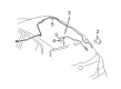
2010 Toyota Yaris Antenna Cable
Part Number: 86101-52340$104.40 MSRP: $146.53You Save: $42.13 (29%)Ships in 1-3 Business DaysProduct Specifications- Other Name: Cord Sub-Assembly, Antenna; Cable
- Part Name Code: 86101
- Item Weight: 1.10 Pounds
- Item Dimensions: 15.3 x 6.1 x 2.1 inches
- Condition: New
- Fitment Type: Direct Replacement
- SKU: 86101-52340
- Warranty: This genuine part is guaranteed by Toyota's factory warranty.

2010 Toyota Yaris Antenna Cable
Part Number: 86101-52410$91.04 MSRP: $127.80You Save: $36.76 (29%)Ships in 1-3 Business DaysProduct Specifications- Other Name: Cord Sub-Assembly, Antenna
- Part Name Code: 86101J
- Item Weight: 0.80 Pounds
- Item Dimensions: 11.9 x 7.7 x 1.8 inches
- Condition: New
- Fitment Type: Direct Replacement
- SKU: 86101-52410
- Warranty: This genuine part is guaranteed by Toyota's factory warranty.

2010 Toyota Yaris Antenna Cable
Part Number: 86101-52590$91.35 MSRP: $128.23You Save: $36.88 (29%)Ships in 1-3 Business DaysProduct Specifications- Other Name: Cord Sub-Assembly, Antenna
- Part Name Code: 86101J
- Item Weight: 0.80 Pounds
- Item Dimensions: 11.6 x 7.6 x 1.9 inches
- Condition: New
- Fitment Type: Direct Replacement
- SKU: 86101-52590
- Warranty: This genuine part is guaranteed by Toyota's factory warranty.

2010 Toyota Yaris Antenna Cable
Part Number: 86101-52600$79.55 MSRP: $111.65You Save: $32.10 (29%)Ships in 1-3 Business DaysProduct Specifications- Other Name: Cord Sub-Assembly, Antenna
- Part Name Code: 86101
- Item Weight: 1.10 Pounds
- Item Dimensions: 15.9 x 6.1 x 2.1 inches
- Condition: New
- Fitment Type: Direct Replacement
- SKU: 86101-52600
- Warranty: This genuine part is guaranteed by Toyota's factory warranty.
2010 Toyota Yaris Antenna Cable
Looking for affordable OEM 2010 Toyota Yaris Antenna Cable? Explore our comprehensive catalogue of genuine 2010 Toyota Yaris Antenna Cable. All our parts are covered by the manufacturer's warranty. Plus, our straightforward return policy and speedy delivery service ensure an unparalleled shopping experience. We look forward to your visit!
2010 Toyota Yaris Antenna Cable Parts Q&A
- Q: How to install the antenna cable sub-assembly for a curtain shield Air Bag on 2010 Toyota Yaris?A: For vehicles with curtain shield Air Bags start by placing the antenna cord section with red positioning tape into claw A of the front side rail spacer before positioning the antenna cord tapes into the two claws of the front and rear side rail spacers. Apply six fresh pieces of tape to secure the antenna cord onto the roof headlining after positioning the antenna cord locating tapes respectively to the roof headlining's markings. Make sure to keep the tape away from the adhesive surface when securing it. The initial process applies the same way for such vehicles by using four new tape pieces instead. Place and secure the No. 4, No. 3, and No. 2 roof headlining pads according to the markings on the roof headlining. The roof headlining assembly installation requires four hook engagement for vehicles with a curtain shield Air Bag before applying the clip and a two claw and four hook approach for vehicles without the Air Bag followed by connector connection and antenna cord installation onto its clamp. Continue with the installation of the No. 2 antenna cord sub-assembly, upper instrument panel sub-assembly, No. 1 switch hole base, glove compartment door assembly, combination meter assembly, instrument cluster finish panel No. 1, instrument panel finish panel ends RH and LH, front pillar garnishes RH and LH, map light assembly, room light assembly, visor holders RH and LH, visor assemblies RH and LH, assist grip sub-assembly and cover, roof headlining service hole cover for vehicles without a curtain shield Air Bag, seat belt anchor cover, rear roof side rail garnishes RH and LH, roof side inner garnishes RH and LH, rear center seat outer belt assembly, center pillar upper garnishes RH and LH, front seat outer belt assemblies RH and LH, seat belt anchor cover cap, deck trim side panel assemblies RH and LH, rear seat assemblies RH and LH for 60/40 split seat types, rear seat leg covers No. 1 and No. 2 for both sides, rear seatback assembly for fold-down seat types, rear seat cushion cover pad sub-assembly, deck floor boxes RH and LH, deck board sub-assembly, package tray trim panel assembly, and finally connect the cable to the negative battery terminal with a torque of 5.4 Nm (55 kgf-cm, 48 in-lbf) and check the SRS warning light.
Related 2010 Toyota Yaris Parts
 2010 Toyota Yaris Headlight Bulb
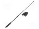 2010 Toyota Yaris Antenna
 2010 Toyota Yaris Fog Light Bulb
 2010 Toyota Yaris Power Window Switch
 2010 Toyota Yaris Spark Plug
 2010 Toyota Yaris TPMS Sensor
 2010 Toyota Yaris ABS Relay
 2010 Toyota Yaris Air Bag Control Module
 2010 Toyota Yaris Air Bag Sensor
 2010 Toyota Yaris Antenna Mast
 2010 Toyota Yaris Back Up Light Switch
 2010 Toyota Yaris Daytime Running Light Relay