×
ToyotaParts- Hello
- Login or Register
- Quick Links
- Live Chat
- Track Order
- Parts Availability
- RMA
- Help Center
- Contact Us
- Shop for
- Toyota Parts
- Scion Parts
My Garage
My Account
Cart
OEM 2010 Scion xD Control Arm
Suspension Arm- Select Vehicle by Model
- Select Vehicle by VIN
Select Vehicle by Model
orMake
Model
Year
Select Vehicle by VIN
For the most accurate results, select vehicle by your VIN (Vehicle Identification Number).
2 Control Arms found


2010 Scion xD Lower Control Arm, Passenger Side
Part Number: 48068-59145$217.77 MSRP: $310.93You Save: $93.16 (30%)Ships in 1-3 Business DaysProduct Specifications- Other Name: Arm Sub-Assembly, Suspension; Suspension Control Arm, Front Right, Front Right Lower; Control Arm Assembly; Arm Sub-Assembly, Front Suspension, Lower Passenger Side; Suspension Control Arm; Control Arm
- Position: Passenger Side
- Replaces: 48068-59095, 48068-59135
- Part Name Code: 48068
- Item Weight: 1.40 Pounds
- Item Dimensions: 21.1 x 3.9 x 17.8 inches
- Condition: New
- Fitment Type: Direct Replacement
- SKU: 48068-59145
- Warranty: This genuine part is guaranteed by Toyota's factory warranty.
2010 Scion xD Lower Control Arm, Driver Side
Part Number: 48069-59135$213.04 MSRP: $304.18You Save: $91.14 (30%)Ships in 1-3 Business DaysProduct Specifications- Other Name: Arm Sub-Assembly, Suspension; Suspension Control Arm, Front Left, Front Left Lower; Control Arm Assembly; Arm Sub-Assembly, Front Suspension, Lower Driver Side; Suspension Control Arm; Control Arm
- Position: Lower Driver Side
- Replaces: 48069-59095, 48069-59125
- Part Name Code: 48069
- Item Weight: 5.30 Pounds
- Item Dimensions: 20.7 x 3.9 x 17.8 inches
- Condition: New
- Fitment Type: Direct Replacement
- SKU: 48069-59135
- Warranty: This genuine part is guaranteed by Toyota's factory warranty.
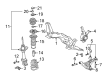
2010 Scion xD Control Arm
Looking for affordable OEM 2010 Scion xD Control Arm? Explore our comprehensive catalogue of genuine 2010 Scion xD Control Arm. All our parts are covered by the manufacturer's warranty. Plus, our straightforward return policy and speedy delivery service ensure an unparalleled shopping experience. We look forward to your visit!
2010 Scion xD Control Arm Parts Q&A
- Q: How to remove the front lower Control Arm on 2010 Scion xD?A: One must begin by taking off the front wheel when removing the front lower suspension arm. Use Special Service Tool: 09960-20010 (spacer B) to install on the threaded lower ball joint section of the left-hand side manual transaxle platform while ensuring its position matches the upper ends. Special Service Tools 09960-20010 and 09961-02010 help separate the lower arm through a process requiring the string connection to the vehicle to avoid drops while ensuring parts A and B maintain parallel alignment before attaching the wrench to its designated area without damaging the lower ball joint dust cover or drive shaft outboard joint boots or front disc brake dust cover. Remove the two bolts followed by the removal of lower arm. Recovery of the hood sub-assembly and front wiper arm head cap before proceeding to uninstall front wiper arm and blade assemblies for left and right sides, hood to cowl top seal, cowl top ventilator louver from both sides, front wiper motor and link as well as front air shutter seal right-hand side, and outer cowl top panel. The procedure requires positioning the wheels in a straight ahead direction before removing the column hole cover silencer sheet together with the steering sliding yoke sub-assembly and No. 1 steering column hole cover sub-assembly. First separate the tie rod end sub-assemblies from both left side and right side then remove front lower suspension arm sub-assemblies from both sides as well as front stabilizer link assemblies from both sides. The engineer should suspend the engine assembly before taking away the front suspension crossmember sub-assembly which will enable front lower suspension arm sub-assembly removal for both left and right sides.
Related 2010 Scion xD Parts
 2010 Scion xD Alignment Bolt
 2010 Scion xD Coil Spring Insulator
 2010 Scion xD Coil Springs
 2010 Scion xD Control Arm Bolt
 2010 Scion xD Front Cross-Member
 2010 Scion xD Shock and Strut Boot
 2010 Scion xD Steering Knuckle
 2010 Scion xD Strut Housing
 2010 Scion xD Sway Bar Kit
 2010 Scion xD Sway Bar Link
 2010 Scion xD Transfer Case Bearing
 2010 Scion xD Wheel Hub