×
ToyotaParts- Hello
- Login or Register
- Quick Links
- Live Chat
- Track Order
- Parts Availability
- RMA
- Help Center
- Contact Us
- Shop for
- Toyota Parts
- Scion Parts
My Garage
My Account
Cart
OEM 2009 Toyota Camry Control Arm
Suspension Arm- Select Vehicle by Model
- Select Vehicle by VIN
Select Vehicle by Model
orMake
Model
Year
Select Vehicle by VIN
For the most accurate results, select vehicle by your VIN (Vehicle Identification Number).
2 Control Arms found


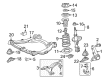
2009 Toyota Camry Control Arm, Lower Driver Side
Part Number: 48069-06150$168.13 MSRP: $238.01You Save: $69.88 (30%)Ships in 1-3 Business DaysProduct Specifications- Other Name: Arm Sub-Assembly, Suspension; Suspension Control Arm, Front Left; Control Arm Assembly; Lower Control Arm; Arm Sub-Assembly, Front Suspension, Lower Driver Side; Suspension Control Arm
- Position: Lower Driver Side
- Part Name Code: 48069
- Item Weight: 7.40 Pounds
- Item Dimensions: 22.5 x 7.0 x 20.5 inches
- Condition: New
- Fitment Type: Direct Replacement
- SKU: 48069-06150
- Warranty: This genuine part is guaranteed by Toyota's factory warranty.


2009 Toyota Camry Control Arm, Passenger Side
Part Number: 48068-06150$158.26 MSRP: $224.04You Save: $65.78 (30%)Ships in 1-3 Business DaysProduct Specifications- Other Name: Arm Sub-Assembly, Suspension; Suspension Control Arm, Front Right; Control Arm Assembly; Lower Control Arm; Arm Sub-Assembly, Front Suspension, Lower Passenger Side; Suspension Control Arm
- Position: Passenger Side
- Part Name Code: 48068
- Item Weight: 8.20 Pounds
- Item Dimensions: 22.9 x 7.1 x 20.3 inches
- Condition: New
- Fitment Type: Direct Replacement
- SKU: 48068-06150
- Warranty: This genuine part is guaranteed by Toyota's factory warranty.
2009 Toyota Camry Control Arm
Looking for affordable OEM 2009 Toyota Camry Control Arm? Explore our comprehensive catalogue of genuine 2009 Toyota Camry Control Arm. All our parts are covered by the manufacturer's warranty. Plus, our straightforward return policy and speedy delivery service ensure an unparalleled shopping experience. We look forward to your visit!
2009 Toyota Camry Control Arm Parts Q&A
- Q: How to replace the Control Arm in the front suspension on 2009 Toyota Camry?A: Eliminating the front suspension lower No. 1 arm demands the removal of the engine assembly with transaxle according to 2AZ-FE or 2GR-FE engine specifications. The next step requires removal of the engine mounting insulator through the separation of its 3 nuts. First remove the front suspension lower No. 1 arm through removal of its 3 bolts and a nut connected to the front frame assembly before disassembling the front lower arm bushing stopper.
Related 2009 Toyota Camry Parts
 2009 Toyota Camry Ball Joint
 2009 Toyota Camry Sway Bar Link
 2009 Toyota Camry Coil Springs
 2009 Toyota Camry Axle Shaft
 2009 Toyota Camry Bump Stop
 2009 Toyota Camry Front Cross-Member
 2009 Toyota Camry Lateral Link
 2009 Toyota Camry Shock And Strut Mount
 2009 Toyota Camry Shock and Strut Boot
 2009 Toyota Camry Steering Knuckle
 2009 Toyota Camry Strut Housing
 2009 Toyota Camry Sway Bar Bushing