×
ToyotaParts- Hello
- Login or Register
- Quick Links
- Live Chat
- Track Order
- Parts Availability
- RMA
- Help Center
- Contact Us
- Shop for
- Toyota Parts
- Scion Parts
My Garage
My Account
Cart
OEM 2009 Scion xB Rack And Pinion
Steering Rack And Pinion- Select Vehicle by Model
- Select Vehicle by VIN
Select Vehicle by Model
orMake
Model
Year
Select Vehicle by VIN
For the most accurate results, select vehicle by your VIN (Vehicle Identification Number).
1 Rack And Pinion found

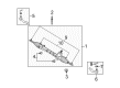
2009 Scion xB Gear Assembly
Part Number: 45510-12471$608.35 MSRP: $891.54You Save: $283.19 (32%)Ships in 1-3 Business DaysProduct Specifications- Other Name: Gear Assembly, Steering; Rack and Pinion Assembly; Steering Gearbox; Steering Gear Assembly
- Replaces: 45510-12470
- Part Name Code: 45510
- Item Weight: 13.60 Pounds
- Item Dimensions: 32.2 x 12.7 x 5.6 inches
- Condition: New
- Fitment Type: Direct Replacement
- SKU: 45510-12471
- Warranty: This genuine part is guaranteed by Toyota's factory warranty.
2009 Scion xB Rack And Pinion
Looking for affordable OEM 2009 Scion xB Rack And Pinion? Explore our comprehensive catalogue of genuine 2009 Scion xB Rack And Pinion. All our parts are covered by the manufacturer's warranty. Plus, our straightforward return policy and speedy delivery service ensure an unparalleled shopping experience. We look forward to your visit!
2009 Scion xB Rack And Pinion Parts Q&A
- Q: How to install the power Rack And Pinion and related components on 2009 Scion xB?A: The first step to install the power steering rack and pinion involves attaching the tie rod end sub-assembly LH to the rack and pinion assembly while fully aligning matchmarks then tightening the lock nut following the toe-in adjustment. Then repeat this step for the tie rod end sub-assembly RH. Place the steering link assembly onto the front suspension crossmember sub-assembly with two bolts and two nuts before torquing up to 138 Nm (1407 kgf-cm, 102 ft-lbf). Install these fasteners from the left side of the vehicle and secure the bolt without turning the nut. Set the matchmarks in place before installing the steering intermediate shaft to the steering link assembly while torquing its bolt to 35 Nm (357 kgf-cm, 26 ft-lbf). You should install the No. 1 steering column hole cover sub-assembly by putting the round hole into position with the protrusion of the steering link assembly. Begin by installing the front suspension crossmember sub-assembly before adding both front suspension member rear braces LH and RH through identical mounting methods. The installation process for front lower suspension arm sub-assemblies should be done in dual sequence including both the LH and RH positions. Use 49 Nm (500 kgf-cm, 36 ft-lbf) torque to connect the tie rod end sub-assembly LH to the steering knuckle before slightly increasing it to 60 degrees when the cotter pin holes are not aligned and installing a fresh cotter pin. Perform the same procedure again on the tie rod end sub-assembly which is situated on the right hand side. The procedure for installing the front stabilizer link assemblies applies to both left-hand and right-hand sides. The production of front suspension member reinforcements LH and RH proceeds according to the same protocol. The next step involves the installation of rear engine under covers LH and RH while also installing the No. 2 and No. 1 engine under covers. The No. 1 steering column hole cover sub-assembly requires the attachment of clip B onto the body before installation with clip A to maintain the undamaged condition of the lip portion. Seriate the No. 2 steering intermediate shaft assembly which will be followed by installation of the column hole cover silencer sheet. The process ends with installing the front wheels then tightening them to 103 Nm (1050 kgf-cm, 76 ft-lbf). Front wheel alignment should also be checked and adjusted.
Related 2009 Scion xB Parts
 2009 Scion xB Steering Wheel
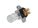 2009 Scion xB Dimmer Switch
 2009 Scion xB Ignition Lock Assembly
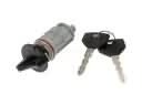 2009 Scion xB Ignition Lock Cylinder
 2009 Scion xB Rack and Pinion Boot
 2009 Scion xB Steering Column
 2009 Scion xB Steering Column Cover
 2009 Scion xB Steering Gear Box
 2009 Scion xB Steering Shaft
 2009 Scion xB Tie Rod End
 2009 Scion xB Wiper Switch