×
ToyotaParts- Hello
- Login or Register
- Quick Links
- Live Chat
- Track Order
- Parts Availability
- RMA
- Help Center
- Contact Us
- Shop for
- Toyota Parts
- Scion Parts
My Garage
My Account
Cart
OEM 2008 Scion xB Rack And Pinion
Steering Rack And Pinion- Select Vehicle by Model
- Select Vehicle by VIN
Select Vehicle by Model
orMake
Model
Year
Select Vehicle by VIN
For the most accurate results, select vehicle by your VIN (Vehicle Identification Number).
1 Rack And Pinion found

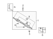
2008 Scion xB Gear Assembly
Part Number: 45510-12471$608.35 MSRP: $891.54You Save: $283.19 (32%)Ships in 1-3 Business DaysProduct Specifications- Other Name: Gear Assembly, Steering; Rack and Pinion Assembly; Steering Gearbox; Steering Gear Assembly
- Replaces: 45510-12470
- Part Name Code: 45510
- Item Weight: 13.60 Pounds
- Item Dimensions: 32.2 x 12.7 x 5.6 inches
- Condition: New
- Fitment Type: Direct Replacement
- SKU: 45510-12471
- Warranty: This genuine part is guaranteed by Toyota's factory warranty.
2008 Scion xB Rack And Pinion
Looking for affordable OEM 2008 Scion xB Rack And Pinion? Explore our comprehensive catalogue of genuine 2008 Scion xB Rack And Pinion. All our parts are covered by the manufacturer's warranty. Plus, our straightforward return policy and speedy delivery service ensure an unparalleled shopping experience. We look forward to your visit!
2008 Scion xB Rack And Pinion Parts Q&A
- Q: How to install the power Rack And Pinion and related components on 2008 Scion xB?A: The power steering rack and pinion installation requires positioning the tie rod end sub-assembly LH on the rack and pinion assembly while aligning matchmarks before tightening the lock nut after toe-in adjustment. Then repeat this procedure for the tie rod end sub-assembly RH. Fix the steering link assembly to the front suspension crossmember sub-assembly with 2 bolts and 2 nuts while applying 138 Nm (1407 kgf-cm, 102 ft-lbf) torque starting from the left vehicle side. Also maintain the nut in its fixed position while screwing the bolt. Position the matchmarks correctly and fasten the steering intermediate shaft onto the steering link assembly through a bolt that reaches 35 Nm (357 kgf-cm, 26 ft-lbf) torque. Here is the order to install the No. 1 steering column hole cover sub-assembly through the steering link assembly protrusion alignment. The installer should begin by mounting the front suspension crossmember sub-assembly then add the front suspension member rear brace LH and RH applying the similar installation method to both sides. The procedure for installing both sides of the front lower suspension arm sub-assembly LH and RH remains the same. The steering knuckle should be joined with the LH tie rod end sub-assembly through a nut that reaches 49 Nm (500 kgf-cm, 36 ft-lbf) torque while additional nut tightening to 60 degrees might be needed to match the cotter pin holes before installing new pins. Execute the same steps for installing the tie rod end sub-assembly RH. The front stabilizer link assembly gets installed on both sides using the same method followed by the installation of front suspension member reinforcement pieces which are also treated equally between the sides. The technician installs the rear engine under covers on left-hand and right-hand sides followed by No. 2 and No. 1 engine under covers. Use clip B to fit the body section before you put the No. 1 steering column hole cover sub-assembly with clip A in place while maintaining attention to the lip part to prevent damages. Mount both No. 2 steering intermediate shaft assemblies to the vehicle body before applying the column hole cover silencer sheet. Complete installation by torquing front wheels to 103 Nm (1050 kgf-cm, 76 ft-lbf) and conduct a check of front wheel alignment.
Related 2008 Scion xB Parts
 2008 Scion xB Steering Wheel
 2008 Scion xB Dimmer Switch
 2008 Scion xB Ignition Lock Assembly
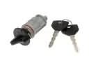 2008 Scion xB Ignition Lock Cylinder
 2008 Scion xB Rack and Pinion Boot
 2008 Scion xB Steering Column
 2008 Scion xB Steering Column Cover
 2008 Scion xB Steering Gear Box
 2008 Scion xB Steering Shaft
 2008 Scion xB Tie Rod End
 2008 Scion xB Wiper Switch