×
ToyotaParts- Hello
- Login or Register
- Quick Links
- Live Chat
- Track Order
- Parts Availability
- RMA
- Help Center
- Contact Us
- Shop for
- Toyota Parts
- Scion Parts
My Garage
My Account
Cart
OEM 2009 Scion tC Air Bag Sensor
Air Bag Impact Sensor- Select Vehicle by Model
- Select Vehicle by VIN
Select Vehicle by Model
orMake
Model
Year
Select Vehicle by VIN
For the most accurate results, select vehicle by your VIN (Vehicle Identification Number).
6 Air Bag Sensors found

2009 Scion tC Sensor, Air Bag, Front Passenger Side
Part Number: 89173-49295$124.77 MSRP: $151.72You Save: $26.95 (18%)Ships in 1-3 Business DaysProduct Specifications- Other Name: Sensor, Air Bag, Front; Sensor, Air Bag, Front Driver Side; Air Bag Sensor
- Position: Front
- Item Weight: 0.70 Pounds
- Item Dimensions: 4.9 x 3.0 x 2.3 inches
- Condition: New
- Fitment Type: Direct Replacement
- SKU: 89173-49295
- Warranty: This genuine part is guaranteed by Toyota's factory warranty.

2009 Scion tC Side Impact Sensor, Passenger Side
Part Number: 89860-21031$197.61 MSRP: $242.34You Save: $44.73 (19%)Ships in 1-3 Business DaysProduct Specifications- Other Name: Sensor Assembly, Side Air Bag; Air Bag Impact Sensor, Front Right; Air Bag Sensor; Side Sensor; Sensor Assembly, Side Air Bag, Passenger Side
- Manufacturer Note: SRS AIR BAG-W(SIDE & CURTAIN SHIELD)
- Position: Passenger Side
- Part Name Code: 89860
- Item Weight: 0.60 Pounds
- Item Dimensions: 4.3 x 2.6 x 2.1 inches
- Condition: New
- Fitment Type: Direct Replacement
- SKU: 89860-21031
- Warranty: This genuine part is guaranteed by Toyota's factory warranty.
2009 Scion tC Side Impact Sensor, Driver Side
Part Number: 89830-21040$197.61 MSRP: $242.34You Save: $44.73 (19%)Ships in 1-3 Business DaysProduct Specifications- Other Name: Sensor Assembly, Side Air Bag; Air Bag Impact Sensor, Front Left; Air Bag Sensor; Side Sensor; Sensor Assembly, Side Air Bag, Driver Side
- Manufacturer Note: SRS AIR BAG-W(SIDE & CURTAIN SHIELD)
- Position: Driver Side
- Part Name Code: 89860A
- Item Weight: 0.60 Pounds
- Item Dimensions: 4.3 x 2.6 x 2.0 inches
- Condition: New
- Fitment Type: Direct Replacement
- SKU: 89830-21040
- Warranty: This genuine part is guaranteed by Toyota's factory warranty.

2009 Scion tC Rear Sensor, Driver Side
Part Number: 89834-21010$120.68 MSRP: $170.84You Save: $50.16 (30%)Ships in 1-3 Business DaysProduct Specifications- Other Name: Sensor, Air Bag, Rear; Air Bag Impact Sensor, Rear Left; Air Bag Sensor; Side Impact Sensor; Sensor, Air Bag, Rear Driver Side
- Manufacturer Note: SRS AIR BAG-W(SIDE & CURTAIN SHIELD)
- Position: Rear Driver Side
- Part Name Code: 89834
- Item Weight: 0.60 Pounds
- Item Dimensions: 4.2 x 2.6 x 2.0 inches
- Condition: New
- Fitment Type: Direct Replacement
- SKU: 89834-21010
- Warranty: This genuine part is guaranteed by Toyota's factory warranty.
2009 Scion tC Rear Sensor, Passenger Side
Part Number: 89833-21010$133.70 MSRP: $189.28You Save: $55.58 (30%)Ships in 1-3 Business DaysProduct Specifications- Other Name: Sensor, Air Bag, Rear; Air Bag Impact Sensor, Rear Right; Air Bag Sensor; Side Impact Sensor; Sensor, Air Bag, Rear Passenger Side
- Manufacturer Note: SRS AIR BAG-W(SIDE & CURTAIN SHIELD)
- Position: Rear Passenger Side
- Part Name Code: 89833
- Item Weight: 0.60 Pounds
- Item Dimensions: 4.3 x 2.5 x 2.0 inches
- Condition: New
- Fitment Type: Direct Replacement
- SKU: 89833-21010
- Warranty: This genuine part is guaranteed by Toyota's factory warranty.

2009 Scion tC Position Sensor, Driver Side
Part Number: 89178-33040$80.57 MSRP: $113.09You Save: $32.52 (29%)Ships in 1-3 Business DaysProduct Specifications- Other Name: Sensor, Seat Position; Seat Track Position Sensor, Left; Sensor, Seat Position Air Bag
- Position: Driver Side
- Part Name Code: 89178A
- Item Weight: 0.50 Pounds
- Item Dimensions: 2.1 x 1.5 x 1.4 inches
- Condition: New
- Fitment Type: Direct Replacement
- SKU: 89178-33040
- Warranty: This genuine part is guaranteed by Toyota's factory warranty.
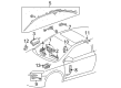
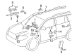
2009 Scion tC Air Bag Sensor
Looking for affordable OEM 2009 Scion tC Air Bag Sensor? Explore our comprehensive catalogue of genuine 2009 Scion tC Air Bag Sensor. All our parts are covered by the manufacturer's warranty. Plus, our straightforward return policy and speedy delivery service ensure an unparalleled shopping experience. We look forward to your visit!
2009 Scion tC Air Bag Sensor Parts Q&A
- Q: What is the role of the Air Bag Sensor in the supplemental restraint system and why is proper service and repair important on 2009 Scion tC?A: As a central element of the supplemental restraint system the impact sensor functions within the center Air Bag sensor assembly to protect vehicle safety features. Service and repair of this assembly need proper attention because it ensures both optimal performance and event reliability during collisions.
Related 2009 Scion tC Parts
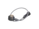 2009 Scion tC Knock Sensor
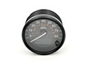 2009 Scion tC Speedometer
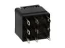 2009 Scion tC ABS Relay
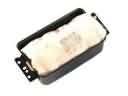 2009 Scion tC Air Bag
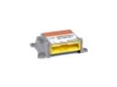 2009 Scion tC Air Bag Control Module
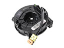 2009 Scion tC Clock Spring
 2009 Scion tC Fuel Pump Gasket
 2009 Scion tC Fuel Tank Strap
 2009 Scion tC Seat Belt
 2009 Scion tC Turn Signal Flasher
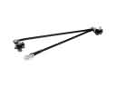 2009 Scion tC Wiper Linkage
 2009 Scion tC Wiper Switch