×
ToyotaParts- Hello
- Login or Register
- Quick Links
- Live Chat
- Track Order
- Parts Availability
- RMA
- Help Center
- Contact Us
- Shop for
- Toyota Parts
- Scion Parts
My Garage
My Account
Cart
OEM 2008 Toyota Sienna Antenna
Radio Antenna- Select Vehicle by Model
- Select Vehicle by VIN
Select Vehicle by Model
orMake
Model
Year
Select Vehicle by VIN
For the most accurate results, select vehicle by your VIN (Vehicle Identification Number).
3 Antennas found


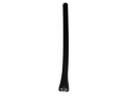
2008 Toyota Sienna Antenna Mast
Part Number: 86309-0C020$38.11 MSRP: $51.41You Save: $13.30 (26%)Ships in 1-3 Business DaysProduct Specifications- Other Name: Pole Sub-Assembly, Pull; Radio Antenna Assembly; Radio Antenna Mast; Antenna Assembly; Mast; Pole Sub-Assembly, Pull Top Antenna
- Replaces: 86309-42060, 86309-AA040, 86309-AA041, 86309-35100, 86309-42040, 86309-42041, 86309-AA042
- Part Name Code: 86309B
- Item Weight: 2.40 Pounds
- Item Dimensions: 36.4 x 4.2 x 4.2 inches
- Condition: New
- Fitment Type: Direct Replacement
- SKU: 86309-0C020
- Warranty: This genuine part is guaranteed by Toyota's factory warranty.


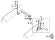
2008 Toyota Sienna Antenna Assembly
Part Number: 86300-AE010$69.19 MSRP: $94.13You Save: $24.94 (27%)Ships in 1-3 Business DaysProduct Specifications- Other Name: Antenna Assembly, With Holder; Radio Antenna Assembly; Antenna; Antenna Assembly, W/Holder
- Part Name Code: 86300
- Item Weight: 0.90 Pounds
- Item Dimensions: 15.6 x 11.3 x 3.0 inches
- Condition: New
- Fitment Type: Direct Replacement
- SKU: 86300-AE010
- Warranty: This genuine part is guaranteed by Toyota's factory warranty.

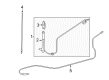
2008 Toyota Sienna Antenna Assembly
Part Number: 86300-AE021$90.98 MSRP: $127.72You Save: $36.74 (29%)Ships in 1-3 Business DaysProduct Specifications- Other Name: Antenna Assembly, Amplifier; Radio Antenna Mast; Antenna; Antenna Assembly, W/Holder
- Part Name Code: 86300
- Item Weight: 2.40 Pounds
- Item Dimensions: 26.3 x 5.3 x 5.3 inches
- Condition: New
- Fitment Type: Direct Replacement
- SKU: 86300-AE021
- Warranty: This genuine part is guaranteed by Toyota's factory warranty.
2008 Toyota Sienna Antenna
Looking for affordable OEM 2008 Toyota Sienna Antenna? Explore our comprehensive catalogue of genuine 2008 Toyota Sienna Antenna. All our parts are covered by the manufacturer's warranty. Plus, our straightforward return policy and speedy delivery service ensure an unparalleled shopping experience. We look forward to your visit!
2008 Toyota Sienna Antenna Parts Q&A
- Q: How to install the amplifier antenna assembly and its components on 2008 Toyota Sienna?A: All installation steps for the amplifier antenna assembly require you to engage 16 clamps and install 3 bolts before connecting the connectors. You should install the roof headlining assembly after installing the amplifier antenna assembly. Fasten the antenna assembly with holder by applying the nut first before installing the bolt and connector attachment. The antenna ornament installation should begin before installing the pull top antenna pole sub-assembly. Installation of the antenna cord sub-assembly requires you to use the 5 clamps. The final step of the installation process includes putting in place the instrument panel safety pad sub-assembly.
Related 2008 Toyota Sienna Parts
 2008 Toyota Sienna Antenna Mast
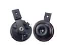 2008 Toyota Sienna Horn
 2008 Toyota Sienna ABS Relay
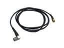 2008 Toyota Sienna Antenna Cable
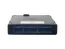 2008 Toyota Sienna Body Control Module
 2008 Toyota Sienna Car Key
 2008 Toyota Sienna Daytime Running Light Relay
 2008 Toyota Sienna Ignition Lock Assembly
 2008 Toyota Sienna Ignition Lock Cylinder
 2008 Toyota Sienna Relay
 2008 Toyota Sienna Relay Block
 2008 Toyota Sienna Transmitter