×
ToyotaParts- Hello
- Login or Register
- Quick Links
- Live Chat
- Track Order
- Parts Availability
- RMA
- Help Center
- Contact Us
- Shop for
- Toyota Parts
- Scion Parts
My Garage
My Account
Cart
OEM 2007 Toyota Sienna Antenna
Radio Antenna- Select Vehicle by Model
- Select Vehicle by VIN
Select Vehicle by Model
orMake
Model
Year
Select Vehicle by VIN
For the most accurate results, select vehicle by your VIN (Vehicle Identification Number).
3 Antennas found


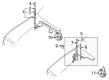
2007 Toyota Sienna Antenna Mast
Part Number: 86309-0C020$38.11 MSRP: $51.41You Save: $13.30 (26%)Ships in 1-3 Business DaysProduct Specifications- Other Name: Pole Sub-Assembly, Pull; Radio Antenna Assembly; Radio Antenna Mast; Antenna Assembly; Mast; Pole Sub-Assembly, Pull Top Antenna
- Replaces: 86309-42060, 86309-AA040, 86309-AA041, 86309-35100, 86309-42040, 86309-42041, 86309-AA042
- Part Name Code: 86309B
- Item Weight: 2.40 Pounds
- Item Dimensions: 36.4 x 4.2 x 4.2 inches
- Condition: New
- Fitment Type: Direct Replacement
- SKU: 86309-0C020
- Warranty: This genuine part is guaranteed by Toyota's factory warranty.


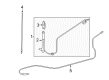
2007 Toyota Sienna Antenna Assembly
Part Number: 86300-AE010$69.19 MSRP: $94.13You Save: $24.94 (27%)Ships in 1-3 Business DaysProduct Specifications- Other Name: Antenna Assembly, With Holder; Radio Antenna Assembly; Antenna; Antenna Assembly, W/Holder
- Part Name Code: 86300
- Item Weight: 0.90 Pounds
- Item Dimensions: 15.6 x 11.3 x 3.0 inches
- Condition: New
- Fitment Type: Direct Replacement
- SKU: 86300-AE010
- Warranty: This genuine part is guaranteed by Toyota's factory warranty.

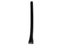
2007 Toyota Sienna Antenna Assembly
Part Number: 86300-AE021$90.98 MSRP: $127.72You Save: $36.74 (29%)Ships in 1-3 Business DaysProduct Specifications- Other Name: Antenna Assembly, Amplifier; Radio Antenna Mast; Antenna; Antenna Assembly, W/Holder
- Part Name Code: 86300
- Item Weight: 2.40 Pounds
- Item Dimensions: 26.3 x 5.3 x 5.3 inches
- Condition: New
- Fitment Type: Direct Replacement
- SKU: 86300-AE021
- Warranty: This genuine part is guaranteed by Toyota's factory warranty.
2007 Toyota Sienna Antenna
Looking for affordable OEM 2007 Toyota Sienna Antenna? Explore our comprehensive catalogue of genuine 2007 Toyota Sienna Antenna. All our parts are covered by the manufacturer's warranty. Plus, our straightforward return policy and speedy delivery service ensure an unparalleled shopping experience. We look forward to your visit!
2007 Toyota Sienna Antenna Parts Q&A
- Q: How to remove and install the Navigation Antenna on 2007 Toyota Sienna?A: The first step when removing the Navigation Antenna requires identification of all bolts, screws and nuts required for instrument panel installations and removals. After disconnecting the negative terminal of the battery you should begin removing the steering wheel cover lower No.2 followed by No.3 and proceed with horn button assembly removal before steering wheel assembly extraction but always keep going to remove the steering column cover and dimmer switch assembly along with the wiper switch. Take out the instrument cluster finish panel sub-assembly when you first remove two clips before pulling it toward the rear and secondly remove the combination meter assembly by unscrewing four screws alongside disconnecting all connectors. The technician should begin by removing 2 bolts from the instrument panel finish panel sub-assembly lower LH and then disconnect the hood lock control cable assembly using its claws and clips and the connectors. Start by unscrewing 4 bolts from the instrument panel safety pad insert sub-assembly No.1 and disconnecting its connector before taking out the glove compartment door stopper sub-assembly and glove compartment door assembly. First detach instrument panel box No.2 from its mounting position by unclipping 2 claws and 4 clips before taking out the instrument side panels (LH and RH) and instrument panel register assemblies No.1 and No.3 as well as the floor carpet covers (center LH and RH) through clips and claw disengagement. Use the moulding remover to detach the instrument cluster finish panel center No.1 since it includes three clips. After that remove the connector. First separate the sub-assembly for the shift lever knob and disconnect the floor shift position indicator housing assembly from the instrument cluster finish panel assembly center by soldering screws and removing connectors. Start by using the specified tool to remove screws and bolts and clips from the instrument cluster finish panel sub-assembly lower center and then take off the instrument cluster finish panel garnish. Remove the 2 screws holding the stereo component speaker assembly before disconnecting its connector followed by removing the navigation receiver assembly, integration control and panel assembly, front pillar garnishes (RH and LH) and instrument panel speaker panel sub-assemblies. You must begin by detaching the front No.1 and No.2 speaker assemblies with their associated defroster nozzle opening plate No.1 then break the shift lever assembly from its original position through removal of four bolts. Terminate the process of instrument panel safety pad sub-assembly removal by unscrewing bolts and screws and a nut, disconnecting all connectors and taking out the instrument panel sub-assembly with passenger Air Bag assembly. The Navigation Antenna assembly installation process begins by releasing 3 clamps and removing 2 screws before executing the reverse order but requires a torque wrench for proper bolt tightening of both the instrument panel safety pad sub-assembly bolt at 20 N.m (204 kgf.cm, 14 ft.lbf) and 4 shift lever assembly bolts at 21 N.m (214 kgf.cm, 12.6 ft.lbf). The procedure ends by reconnecting the battery negative terminal and inspecting the horn button and SRS warning light.
Related 2007 Toyota Sienna Parts
 2007 Toyota Sienna Antenna Mast
 2007 Toyota Sienna Horn
 2007 Toyota Sienna ABS Relay
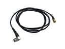 2007 Toyota Sienna Antenna Cable
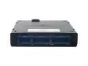 2007 Toyota Sienna Body Control Module
 2007 Toyota Sienna Car Key
 2007 Toyota Sienna Daytime Running Light Relay
 2007 Toyota Sienna Ignition Lock Assembly
 2007 Toyota Sienna Ignition Lock Cylinder
 2007 Toyota Sienna Relay
 2007 Toyota Sienna Relay Block
 2007 Toyota Sienna Transmitter