×
ToyotaParts- Hello
- Login or Register
- Quick Links
- Live Chat
- Track Order
- Parts Availability
- RMA
- Help Center
- Contact Us
- Shop for
- Toyota Parts
- Scion Parts
My Garage
My Account
Cart
OEM 2008 Toyota Sequoia Exhaust Manifold
Engine Exhaust Manifold- Select Vehicle by Model
- Select Vehicle by VIN
Select Vehicle by Model
orMake
Model
Year
Select Vehicle by VIN
For the most accurate results, select vehicle by your VIN (Vehicle Identification Number).
4 Exhaust Manifolds found


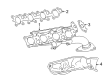
2008 Toyota Sequoia Exhaust Manifold, Driver Side
Part Number: 17105-38011$477.14 MSRP: $699.26You Save: $222.12 (32%)Ships in 1-3 Business DaysProduct Specifications- Other Name: Manifold Sub-Assembly, Exhaust; Exhaust Manifold, Left; Manifold Sub-Assembly, Exhaust, Driver Side
- Position: Driver Side
- Replaces: 17105-38010
- Part Name Code: 17105
- Item Weight: 1.40 Pounds
- Item Dimensions: 16.2 x 7.9 x 5.3 inches
- Condition: New
- Fitment Type: Direct Replacement
- SKU: 17105-38011
- Warranty: This genuine part is guaranteed by Toyota's factory warranty.


2008 Toyota Sequoia Exhaust Manifold, Driver Side
Part Number: 17105-50210$333.64 MSRP: $476.37You Save: $142.73 (30%)Ships in 1-3 Business DaysProduct Specifications- Other Name: Manifold Sub-Assembly, Exhaust; Exhaust Manifold, Left; Manifold Sub-Assembly, Exhaust, Driver Side
- Position: Driver Side
- Part Name Code: 17105
- Item Weight: 11.00 Pounds
- Item Dimensions: 26.3 x 9.2 x 7.2 inches
- Condition: New
- Fitment Type: Direct Replacement
- SKU: 17105-50210
- Warranty: This genuine part is guaranteed by Toyota's factory warranty.

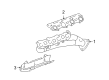
2008 Toyota Sequoia Exhaust Manifold, Passenger Side
Part Number: 17104-50220$333.64 MSRP: $476.37You Save: $142.73 (30%)Ships in 1-3 Business DaysProduct Specifications- Other Name: Manifold Sub-Assembly, Exhaust; Exhaust Manifold, Right; Manifold Sub-Assembly, Exhaust, Passenger Side
- Position: Passenger Side
- Part Name Code: 17104
- Item Weight: 8.20 Pounds
- Item Dimensions: 26.8 x 9.5 x 7.4 inches
- Condition: New
- Fitment Type: Direct Replacement
- SKU: 17104-50220
- Warranty: This genuine part is guaranteed by Toyota's factory warranty.

2008 Toyota Sequoia Exhaust Manifold, Passenger Side
Part Number: 17104-38011$416.99 MSRP: $611.10You Save: $194.11 (32%)Ships in 1-3 Business DaysProduct Specifications- Other Name: Manifold Sub-Assembly, Exhaust; Exhaust Manifold, Right; Manifold Sub-Assembly, Exhaust, Passenger Side
- Position: Passenger Side
- Replaces: 17104-38010
- Part Name Code: 17104
- Item Weight: 12.80 Pounds
- Item Dimensions: 18.0 x 11.7 x 8.2 inches
- Condition: New
- Fitment Type: Direct Replacement
- SKU: 17104-38011
- Warranty: This genuine part is guaranteed by Toyota's factory warranty.
2008 Toyota Sequoia Exhaust Manifold
Looking for affordable OEM 2008 Toyota Sequoia Exhaust Manifold? Explore our comprehensive catalogue of genuine 2008 Toyota Sequoia Exhaust Manifold. All our parts are covered by the manufacturer's warranty. Plus, our straightforward return policy and speedy delivery service ensure an unparalleled shopping experience. We look forward to your visit!
2008 Toyota Sequoia Exhaust Manifold Parts Q&A
- Q: How to remove the exhaust manifold on 2008 Toyota Sequoia?A: A proper removal of the exhaust manifold on a 2UZ-FE engine starts by eliminating the No. 1 engine under cover followed by draining engine coolant. Move on to the throttle body cover sub-assembly removal while following it with the air cleaner hose assembly then air cleaner assembly removal. The repair requires removal of five clips from the front fender apron seal rear LH before repeating the process for its counterpart with six clips on the front fender apron seal LH. The maintenance starts with removing the No. 2 air hose and No. 3 air tube from Bank 1 before taking out the air switching valve assembly for Bank 1. You should repeat this process once to detach the front fender apron seal rear RH and front fender apron seal RH by taking out their corresponding clips. Unfasten the clip to remove the engine oil level dipstick guide together with heater outlet water hose and No. 5 water by-pass hose. Detach the water by-pass pipe assembly from the transmission oil cooler following bolt removal of 3 bolts and disconnecting 2 water hoses. The technician disconnects the Bank 2 No. 2 air injection system hose together with No. 2 air tube and air switching valve assembly. Disassemble the front exhaust pipe assembly in combination with the propeller shaft heat insulator and front propeller shaft assembly for 4WD. Remove the front No. 2 exhaust pipe assembly before proceeding to detach the No. 1 exhaust manifold heat insulator through its 4 bolt removal. To remove the exhaust manifold sub-assembly RH contractors need to unfasten 8 nuts and remove the gasket followed by taking off the No. 2 exhaust manifold heat insulator with 4 bolts installed and concluding by unfastening the 8 nuts and gasket of the exhaust manifold sub-assembly LH.
Related 2008 Toyota Sequoia Parts
 2008 Toyota Sequoia Catalytic Converter
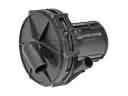 2008 Toyota Sequoia Air Injection Pump
 2008 Toyota Sequoia Muffler
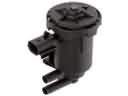 2008 Toyota Sequoia Canister Purge Valve
 2008 Toyota Sequoia Diverter Valve
 2008 Toyota Sequoia Exhaust Flange Gasket
 2008 Toyota Sequoia Exhaust Hanger
 2008 Toyota Sequoia Exhaust Heat Shield
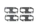 2008 Toyota Sequoia Exhaust Manifold Gasket
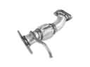 2008 Toyota Sequoia Exhaust Pipe
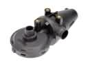 2008 Toyota Sequoia PCV Valve
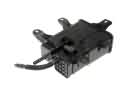 2008 Toyota Sequoia Vapor Canister