×
ToyotaParts- Hello
- Login or Register
- Quick Links
- Live Chat
- Track Order
- Parts Availability
- RMA
- Help Center
- Contact Us
- Shop for
- Toyota Parts
- Scion Parts
My Garage
My Account
Cart
OEM 2008 Toyota Highlander Antenna Cable
Radio Antenna Cable- Select Vehicle by Model
- Select Vehicle by VIN
Select Vehicle by Model
orMake
Model
Year
Select Vehicle by VIN
For the most accurate results, select vehicle by your VIN (Vehicle Identification Number).
4 Antenna Cables found

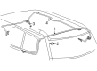
2008 Toyota Highlander Antenna Cable, Rear
Part Number: 86101-0E160$138.99 MSRP: $196.76You Save: $57.77 (30%)Ships in 1-3 Business DaysProduct Specifications- Other Name: Cord Sub-Assembly, Antenna; Antenna Cable, Rear, Upper
- Position: Rear
- Replaces: 86101-48650
- Part Name Code: 86101J
- Item Weight: 0.80 Pounds
- Item Dimensions: 11.9 x 7.7 x 1.9 inches
- Condition: New
- Fitment Type: Direct Replacement
- SKU: 86101-0E160
- Warranty: This genuine part is guaranteed by Toyota's factory warranty.

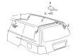
2008 Toyota Highlander Antenna Cable, Front
Part Number: 86101-0E220$143.57 MSRP: $203.25You Save: $59.68 (30%)Ships in 1-3 Business DaysProduct Specifications- Other Name: Cord Sub-Assembly, Antenna; Antenna Cable, Front, Lower
- Position: Front
- Replaces: 86101-48730
- Part Name Code: 86101
- Item Weight: 1.10 Pounds
- Item Dimensions: 15.3 x 5.9 x 2.1 inches
- Condition: New
- Fitment Type: Direct Replacement
- SKU: 86101-0E220
- Warranty: This genuine part is guaranteed by Toyota's factory warranty.

2008 Toyota Highlander Antenna Cable, Lower
Part Number: 86101-0E200$143.57 MSRP: $203.25You Save: $59.68 (30%)Ships in 1-3 Business DaysProduct Specifications- Other Name: Cord Sub-Assembly, Antenna; Antenna Cable, Front, Lower
- Position: Lower
- Replaces: 86101-48710
- Part Name Code: 86101
- Item Weight: 1.10 Pounds
- Item Dimensions: 15.4 x 6.0 x 2.1 inches
- Condition: New
- Fitment Type: Direct Replacement
- SKU: 86101-0E200
- Warranty: This genuine part is guaranteed by Toyota's factory warranty.

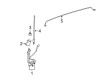
2008 Toyota Highlander Cable
Part Number: 86101-0E140$131.00 MSRP: $185.45You Save: $54.45 (30%)Ships in 1-3 Business DaysProduct Specifications- Other Name: Cord Sub-Assembly, Antenna; Antenna Cable
- Replaces: 86101-48700
- Part Name Code: 86101
- Item Weight: 1.10 Pounds
- Item Dimensions: 15.4 x 6.1 x 2.1 inches
- Condition: New
- Fitment Type: Direct Replacement
- SKU: 86101-0E140
- Warranty: This genuine part is guaranteed by Toyota's factory warranty.
2008 Toyota Highlander Antenna Cable
Looking for affordable OEM 2008 Toyota Highlander Antenna Cable? Explore our comprehensive catalogue of genuine 2008 Toyota Highlander Antenna Cable. All our parts are covered by the manufacturer's warranty. Plus, our straightforward return policy and speedy delivery service ensure an unparalleled shopping experience. We look forward to your visit!
2008 Toyota Highlander Antenna Cable Parts Q&A
- Q: How to remove the radio antenna cable (for Glass Antenna Type) on 2008 Toyota Highlander?A: The procedure to remove the audio / visual: radio antenna cord (for glass antenna type) starts with ensuring the front wheels face forward before disconnecting the negative battery cable for 90 seconds to avoid air bag activation. After connecting the cable some systems need to be initialized. Begin by removing lower NO. 3 steering wheel cover followed by lower NO. 2 steering wheel cover together with steering pad and steering wheel assembly and steering column cover. The technicians should remove the turn signal switch assembly along with its spiral cable sub-assembly and also extract the instrument cluster finish panel assembly combining with the combination meter assembly and both types of center instrument panel register assembly and both versions of center instrument cluster finish panel assembly (with and without smart key system). The technician should extract the heater control accessory assembly for manual engines before extracting the air conditioning control assembly for automatic engines. This operation should continue with the removal of radio receiver assemblies with brackets for manual and navigation systems. First dismantle the scuff plates from the front doors (both left hand and right hand sides), then detach the side trim sub-assemblies from the cowl region (lh and rh) and the lower instrument panel finish panels (manual and automatic air conditioning systems) followed by the instrument panel sub-assembly. Remove the upper console panel sub-assembly together with the console box duct when no rear air conditioning system exists as well as both console box assemblies that do and do not have this system. The next sequence requires technicians to remove the front NO. 1 and NO. 2 console box inserts together with the engine switch that includes the smart key system as well as the front door opening trim weather strips for both LH and RH sides and front pillar garnishes for both LH and RH positions along with the NO. 1 instrument panel speaker panel sub-assembly and front NO. 2 speaker assemblies (both LH and rh) and instrument panel wire disconnection. The removal process includes taking out the instrument panel safety pad assembly and the NO. 1 and NO. 4 heater to register ducts and the side NO. 1 and NO. 2 defroster nozzle ducts along with the defroster nozzle assembly and the center heater to register sub duct. To remove the navigation antenna assembly with the navigation system feature the 9 clamps must be disengaged from the antenna cord sub-assembly. Proceed by removing the rear center seat assembly then disassemble the rear seat headrest assembly on both left-hand-side and right-hand-side with additional steps involving removal of rear seat track bracket covers (both LH and rh) and rear outer and inner track bracket covers (both LH and rh) and rear seat leg side covers (both LH and rh) after unlocking the rear NO. 1 seat lock cable assemblies (both LH and rh). The next stage involves removing the rear door scuff plates (both LH and rh), rear door opening trim weather strips (both LH and rh), lower center pillar garnishes (both LH and rh), disconnecting the front seat outer belt assemblies (both LH and rh) and extracting the center pillar garnishes (both LH and rh). Disassemble the deck board components and separate the NO. 3 and NO. 2 deck board sub-frames, tonneau cover assembly (with tonneau cover), rear NO. 1 floor board (without rear NO. 2 seat), rear seat side covers (both left and right) as well as deck side trim boxes (both left and right), jack carrier support, jack carrier cushion, jack assembly, and jack carrier assembly. The procedure requires all components of the rear deck floor board assemblies and rear mat assembly to be taken out including the two options both with and without rear NO. 2 seat. The rear deck floor box and the rear NO. 2 seat inner belt assembly (with rear NO. 2 seat) must also be removed. Next, disconnect both rear seat lap type belt assemblies (lh and rh) followed by the removal of the rear NO. 2 seat assembly (with rear NO. 2 seat). Finally, remove the rear floor finish plate, deck side trim covers (both LH and rh), deck side trims (both LH and rh), side trim covers (both LH and rh), rear room temperature sensor (with rear automatic air conditioning system), rear combination light service covers (both LH and rh), and the front deck side trim covers (both LH and rh), disconnect the rear NO. 1 seat outer belt assemblies (both LH and rh), and remove the deck trim side panel assemblies (both LH and rh), quarter pillar garnishes (both LH and rh), roof side inner garnish assemblies (both LH and RH, with and without rear NO. 2 seat), roof console box assembly, visor bracket covers (both LH and rh), visor assemblies (both LH and rh), inner rear view mirror stay holder cover (with ec mirror), NO. 1 room light assemblies (for standard and independent type), NO. 2 room light assembly, television base and display assemblies (with rear seat entertainment system), front and rear assist grip sub-assemblies (without sliding roof), assist grip assembly (with sliding roof), roof headlining trim clip stopper, sun roof opening trim moulding (with sliding roof), roof headlining assemblies (with and without sliding roof), and finally, the NO. 2 antenna cord sub-assembly by peeling the tape only as necessary to allow removal.
Related 2008 Toyota Highlander Parts
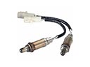 2008 Toyota Highlander Oxygen Sensor
 2008 Toyota Highlander Antenna
 2008 Toyota Highlander Camshaft Position Sensor
 2008 Toyota Highlander Horn
 2008 Toyota Highlander Air Bag Sensor
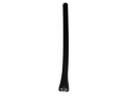 2008 Toyota Highlander Antenna Mast
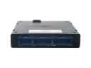 2008 Toyota Highlander Body Control Module
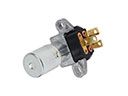 2008 Toyota Highlander Dimmer Switch
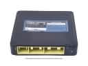 2008 Toyota Highlander Engine Control Module
 2008 Toyota Highlander Neutral Safety Switch
 2008 Toyota Highlander Relay
 2008 Toyota Highlander Transmitter