×
ToyotaParts- Hello
- Login or Register
- Quick Links
- Live Chat
- Track Order
- Parts Availability
- RMA
- Help Center
- Contact Us
- Shop for
- Toyota Parts
- Scion Parts
My Garage
My Account
Cart
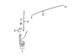
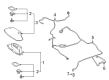
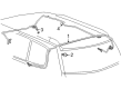
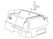
OEM Toyota Highlander Antenna Cable
Radio Antenna Cable- Select Vehicle by Model
- Select Vehicle by VIN
Select Vehicle by Model
orMake
Model
Year
Select Vehicle by VIN
For the most accurate results, select vehicle by your VIN (Vehicle Identification Number).
48 Antenna Cables found

Toyota Highlander Cable Part Number: 86101-0E140
$133.70 MSRP: $189.28You Save: $55.58 (30%)Ships in 1-3 Business Days
Toyota Highlander Antenna Cable Part Number: 86101-0EA41
$141.58 MSRP: $200.42You Save: $58.84 (30%)Ships in 1-2 Business DaysToyota Highlander Antenna Cable, Front Part Number: 86101-0EA40
$141.69 MSRP: $200.58You Save: $58.89 (30%)Ships in 1-3 Business DaysToyota Highlander Antenna Cable, Lower Part Number: 86101-0E310
$143.22 MSRP: $202.75You Save: $59.53 (30%)Ships in 1-3 Business Days
Toyota Highlander Antenna Cable, Rear Part Number: 86101-0E160
$138.99 MSRP: $196.76You Save: $57.77 (30%)Ships in 1-3 Business Days
Toyota Highlander Antenna Cable, Front Part Number: 86101-48D50
$139.25 MSRP: $197.13You Save: $57.88 (30%)Ships in 1-3 Business DaysToyota Highlander Antenna Cable, Front Part Number: 86101-48D40
$139.25 MSRP: $197.13You Save: $57.88 (30%)Ships in 1-3 Business DaysToyota Highlander Antenna Cable, Front Part Number: 86101-0E220
$143.57 MSRP: $203.25You Save: $59.68 (30%)Ships in 1-3 Business Days
Toyota Highlander Antenna Cable, Lower Part Number: 86101-0E200
$147.92 MSRP: $209.40You Save: $61.48 (30%)Ships in 1-3 Business Days
Toyota Highlander Antenna Cable, Rear Part Number: 86101-48490
$144.49 MSRP: $204.55You Save: $60.06 (30%)Ships in 1-3 Business Days
Toyota Highlander Antenna Cable, Center Part Number: 86101-0EB20
$145.43 MSRP: $205.87You Save: $60.44 (30%)Ships in 1-3 Business Days
Toyota Highlander Antenna Cable, Front Part Number: 86101-0E350
$149.46 MSRP: $211.58You Save: $62.12 (30%)Ships in 1-3 Business DaysToyota Highlander Antenna Cable, Rear Part Number: 86101-48270
$152.33 MSRP: $215.64You Save: $63.31 (30%)Ships in 1-3 Business Days
Toyota Highlander Antenna Cable, Front Part Number: 86101-48250
$156.83 MSRP: $222.01You Save: $65.18 (30%)Ships in 1-3 Business DaysToyota Highlander Antenna Cable, Front Part Number: 86101-0EE60
$161.76 MSRP: $229.00You Save: $67.24 (30%)Ships in 1-3 Business DaysToyota Highlander Antenna Cable, Front Part Number: 86101-0EE20
$166.72 MSRP: $236.01You Save: $69.29 (30%)Ships in 1-3 Business DaysToyota Highlander Antenna Cable, Front Part Number: 86101-0E320
$163.83 MSRP: $231.93You Save: $68.10 (30%)Ships in 1-3 Business Days
Toyota Highlander Antenna Cable, Rear Part Number: 86101-48C31
$168.21 MSRP: $238.13You Save: $69.92 (30%)Ships in 1-3 Business DaysToyota Highlander Antenna Cable, Upper Part Number: 86101-0E330
$173.30 MSRP: $245.33You Save: $72.03 (30%)Ships in 1-3 Business Days
Toyota Highlander Antenna Cable, Center Part Number: 86101-0E500
$141.69 MSRP: $200.58You Save: $58.89 (30%)Ships in 1-3 Business Days
| Page 1 of 3 |Next >
1-20 of 48 Results
Toyota Highlander Antenna Cable
Choose genuine Antenna Cable that pass strict quality control tests. You can trust the top quality and lasting durability. Shopping for OEM Antenna Cable for your Toyota Highlander? Our website is your one-stop destination. We stock an extensive selection of genuine Toyota Highlander parts. The price is affordable so you can save more. It only takes minutes to browse and find the exact fit. Easily add to cart and check out fast. Our hassle-free return policy will keep you stress-free. We process orders quickly for swift delivery. Your parts will arrive faster, so you can get back on the road sooner.
Toyota Highlander Antenna Cable Parts and Q&A
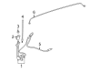
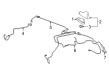
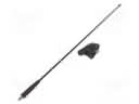
- Q: How to remove the radio antenna cable for Pole Antenna Type on Toyota Highlander?A:Users Should Start Dismantling The Radio Antenna Cord (For Pole Antenna Type) When Both Front Wheels Face Straight Ahead And They Terminate The Cable From The Negative Battery Terminal While Waiting 90 Seconds To Stop Air Bag Deployment. This Cable Connection System Demands A Setup Procedure After The Cable Reattachment. First Disconnect The Lower No. 3 Steering Wheel Cover Together With The Lower No. 2 Steering Wheel Cover And Then Remove The Steering Pad Before Taking Out The Steering Wheel Assembly And Steering Column Cover. The Service Technician Should Eliminate Turn Signal Switch Assembly With Spiral Cable Sub-Assembly, Instrument Cluster Finish Panel Assembly, Combination Meter Assembly, Center Instrument Panel Register Assembly, Center Instrument Cluster Finish Panel Assembly, Heater Control And Accessory Assembly, And Radio Receiver Assembly With Bracket Before The Front Wheels Are Aligned Straight Ahead. Proceed To Remove The Front Door Scuff Plate Lh, Cowl Side Trim Sub-Assembly Lh, Lower Instrument Panel Finish Panel Sub-Assembly, Front Door Scuff Plate Rh, Cowl Side Trim Sub-Assembly Rh, No. 2 Instrument Panel Under Cover Sub-Assembly, Lower Instrument Panel Sub-Assembly, Upper Console Panel Sub-Assembly, No. 2 Console Box Duct (W/O Rear Air Conditioning System), Lower Rear Console Box, Console Box Assembly (W/O Rear Air Conditioning System), Console Box Assembly (W/ Rear Air Conditioning System), Front No. 1 Console Box Insert, Front No. 2 Console Box Insert, And Disconnect The Front Door Opening Trim Weather Strip Lh. Workers Need To Remove The Front Pillar Garnish Lh Followed By Disconnecting The Front Door Opening Trim Weather Strip Rh And Concluding By Removing The Front Pillar Garnish Rh. The Service Technician Should Begin By Extracting The No. 1 Instrument Panel Speaker Panel Sub-Assembly Along With Front No. 2 Speaker Assembly (For Lh Side) And No. 2 Instrument Panel Speaker Panel Sub-Assembly And Front No. 2 Speaker Assembly (For Rh Side). The Headlamp Wiring First Needs To Be Detached Before The Instrument Panel Safety Pad Followed By Heater And Defrost Duct Assemblies For Removal. Close This Section With The Antenna Connector Detachment. The Next Step Is To Remove The Antenna Cord Sub-Assembly By Unhooking All Nine Clamps Before Separating The Engine Under Cover Assembly And No. 1 Engine Under Cover With Additional Removal Of Front Fender Moulding Sub-Assembly, Front Fender Liner, Pull Top Antenna Pole Sub-Assembly, Antenna Nut, Fender Antenna Assembly And Antenna Ornament.
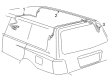
- Q: How to Properly Install an Antenna Cable on Toyota Highlander?A:Start by installing the No. 2 Antenna cord sub-assembly while verifying double-sided tape stickiness; if required, replace tape by stripping old tape then avoiding the adhesive by aliging new tape markings with the roof headlining before removing backing. Install the antenna cord by attaching it to the roof headlining assembly at the front of the vehicle while matching the marking tape to the protrusion and securing with tape. The roof headlining assembly installation takes place next with or without the sliding roof while the worker follows procedures for both sides The next sequence involves assembling the television devices and television base units, room light elements, inner rear view mirror stay holder shield and visor supports alongside brackets, roof console storing bins, roof interior garnishes, quarter provisions and secondary deck frameworks and multiple attaching trimmings before connecting rear outer safety belts and finally mounting rear lamp assembly units. Finish the installation process by attaching the rear lap type Seat Belts then the rear no. 2 seat inner belt followed by the rear deck floor box before fitting the deck floor board and all side trim boxes including seat lock cables assessment of rear seat slide adjuster locks. The process concludes with installing rear seat headrest assemblies and antenna cord sub-assembly as well as navigation antenna assembly when needed, along with various duct and panel assemblies to secured all functional components.


Related Toyota Highlander Parts
 Toyota Highlander Antenna
 Toyota Highlander Door Lock Actuator Motor
 Toyota Highlander ABS Control Module
 Toyota Highlander Air Bag Control Module
 Toyota Highlander Antenna Mast
 Toyota Highlander Car Key
 Toyota Highlander Cooling Fan Relay
 Toyota Highlander Daytime Running Light Relay
 Toyota Highlander Fuse
 Toyota Highlander Hazard Warning Switch
 Toyota Highlander Heater Control Valve
 Toyota Highlander Ignition Lock Assembly