×
ToyotaParts- Hello
- Login or Register
- Quick Links
- Live Chat
- Track Order
- Parts Availability
- RMA
- Help Center
- Contact Us
- Shop for
- Toyota Parts
- Scion Parts
My Garage
My Account
Cart
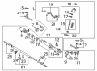
OEM 2007 Toyota Sequoia Rack And Pinion
Steering Rack And Pinion- Select Vehicle by Model
- Select Vehicle by VIN
Select Vehicle by Model
orMake
Model
Year
Select Vehicle by VIN
For the most accurate results, select vehicle by your VIN (Vehicle Identification Number).
2 Rack And Pinions found

2007 Toyota Sequoia Rack, Front
Part Number: 44204-0C011$580.43 MSRP: $850.63You Save: $270.20 (32%)Ships in 1-3 Business DaysProduct Specifications- Other Name: Rack Sub-Assembly, Power; Rack And Pinion Rack Gear, Front; Steering Gearbox; Steering Rack; Rack Sub-Assembly, Power Steering
- Position: Front
- Part Name Code: 44204
- Item Weight: 5.70 Pounds
- Item Dimensions: 32.1 x 3.3 x 2.8 inches
- Condition: New
- Fitment Type: Direct Replacement
- SKU: 44204-0C011
- Warranty: This genuine part is guaranteed by Toyota's factory warranty.

2007 Toyota Sequoia Steering Gear
Part Number: 44250-0C041$722.76 MSRP: $1059.21You Save: $336.45 (32%)Product Specifications- Other Name: Gear Assembly, Power Steering; Rack and Pinion Assembly; Steering Gearbox; Rack & Pinion; Gear Assembly; Gear Assembly, Power Steering(For Rack & Pinion)
- Manufacturer Note: W(REAR STABILIZER)
- Replaces: 44250-0C050, 44250-0C020
- Part Name Code: 44250
- Item Weight: 1.40 Pounds
- Item Dimensions: 3.4 x 3.2 x 3.5 inches
- Condition: New
- Fitment Type: Direct Replacement
- SKU: 44250-0C041
- Warranty: This genuine part is guaranteed by Toyota's factory warranty.
2007 Toyota Sequoia Rack And Pinion
Looking for affordable OEM 2007 Toyota Sequoia Rack And Pinion? Explore our comprehensive catalogue of genuine 2007 Toyota Sequoia Rack And Pinion. All our parts are covered by the manufacturer's warranty. Plus, our straightforward return policy and speedy delivery service ensure an unparalleled shopping experience. We look forward to your visit!
2007 Toyota Sequoia Rack And Pinion Parts Q&A
- Q: How to service and repair the power Rack And Pinion on 2007 Toyota Sequoia?A: Start rack and pinion power steering work by taking off the negative battery connector then waiting 90 seconds to stop Air Bags from activating. Align front wheels to straight posture before taking off the steering wheel garnish and hardware. Take out the left and right tie rod end sub-assemblies, No. 2 intermediate shaft assembly, and clamp plate according to their bolt release. Detach the pressure lines from the tubing with SST 09023-12701 and take out the power steering rack and pinion assembly by first removing the bolt, stud bolt, and nut from the bracket before removing the two set bolts, PS rack and pinion assembly, washer, and final nut. Unscrew the turn pressure tube with tool SST 09023-38401 and go ahead with O-ring removal before taking apart the rack and pinion unit. Affix the power steering rack and pinion assembly to a vise using SST 09612-00012 to keep it secure while removing the left and right tie rod end sub-assemblies and marking their positions for reinstallation. Handle clips rack boots and clamps delicately to protect them. Unfasten the washer at the steering rack end using SST 09922-10010 then remove it together with SST. Also detach the rack guide spring cap lock nut using the same SST tool. Use a hexagon tool to remove the rack guide spring cap then pull off the rack guide spring and sub-assembly from the housing. Complete the procedure by taking out the rack housing cap using SST 09816-30010. Detach the self-locking nut with SST 09616-00011 and take away the dust cover along with the control valve housing containing the control valve assembly. Note the removed parts' positions for installation afterward. Press out the steering rack with its bushing using tool number SST 09950-70010 (09951-07200) to remove the O-ring and cylinder end stopper with tool SST 09631-16010. Verify the steering rack shows no more than 0.09 mm (0.0035 inch) runout and multiple 0.09 mm (0.0035 inch) damage on teeth by inspecting the rack parts. Press the new oil seal into place with the specified SST 09950-60010 tools (09951-00180, 09951-00320, 09952-06010) after putting in the new bearing with parts 09950-60010 (09951-00250), 09950-70010 (09951-07150). Before pressing in the new oil seal parts apply power steering fluid to the lip and grease to the bearing. Also install the teflon rings and O-rings while taking care not to harm the oil seal grooves. Reassemble parts using power steering fluid or grease as coating agent and install the oil seal through SST 09950-60010 (09951-00330 and 09952-06010). Finally, place the steering rack aided by SST 09631-20051. Put the bushing and end stopper in place before evaluating pressure leakage with tool SST 09631-12071. Fit the control valve assembly while taking care to guard the oil seal lip and inserting the oil seal with SST 09612-22011. Use new bolts to fasten the control valve housing with its gasket before placing the self-locking nut and dust cover on top. Yield the rack guide sub-assembly over the cap then insert spring and guide top part. Adjust the total preload system and put the rack guide spring cap into place with proper nut torque settings. Set the rack end in line with the claw washer before adding the rack boot clamp and snap ring. Rejoin the tie rod ends before setting toe-in angle and tightening the nuts. Fit the grommet and power steering rack and pinion assembly before linking the return and pressure feed tubes with tool SST 09023-12701. Simply link all parts including the clamp platform, intermediate shaft, and tie rod ends while aligning the front wheels directly ahead. Place the spiral cable spindle correctly before adding the steering wheel hardware and bled out the power steering regulation. Verify that the steering wheel returns to its center position and tighten its set nut before adding the steering wheel pad. End by realigning the front wheels then fix the battery connection followed by sensor calibration and setup.
Related 2007 Toyota Sequoia Parts
 2007 Toyota Sequoia Power Steering Pump
 2007 Toyota Sequoia Steering Angle Sensor
 2007 Toyota Sequoia Steering Wheel
 2007 Toyota Sequoia Drag Link
 2007 Toyota Sequoia Power Steering Control Valve
 2007 Toyota Sequoia Power Steering Hose
 2007 Toyota Sequoia Power Steering Reservoir
 2007 Toyota Sequoia Rack and Pinion Boot
 2007 Toyota Sequoia Steering Column Cover
 2007 Toyota Sequoia Steering Gear Box
 2007 Toyota Sequoia Steering Shaft
 2007 Toyota Sequoia Tie Rod End