×
ToyotaParts- Hello
- Login or Register
- Quick Links
- Live Chat
- Track Order
- Parts Availability
- RMA
- Help Center
- Contact Us
- Shop for
- Toyota Parts
- Scion Parts
My Garage
My Account
Cart
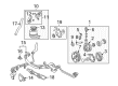
OEM 2007 Toyota Sequoia Power Steering Pump
Power Steering Pump Unit- Select Vehicle by Model
- Select Vehicle by VIN
Select Vehicle by Model
orMake
Model
Year
Select Vehicle by VIN
For the most accurate results, select vehicle by your VIN (Vehicle Identification Number).
1 Power Steering Pump found


 Product Specifications
- Other Name: Pump Assembly, Vane
- Replaces: 44320-0C020, 44320-0C030
- Part Name Code: 44320
- Item Weight: 8.30 Pounds
- Item Dimensions: 10.5 x 7.3 x 7.1 inches
- Condition: New
- Fitment Type: Direct Replacement
- SKU: 44310-0C030
- Warranty: This genuine part is guaranteed by Toyota's factory warranty.
2007 Toyota Sequoia Power Steering Pump
Looking for affordable OEM 2007 Toyota Sequoia Power Steering Pump? Explore our comprehensive catalogue of genuine 2007 Toyota Sequoia Power Steering Pump. All our parts are covered by the manufacturer's warranty. Plus, our straightforward return policy and speedy delivery service ensure an unparalleled shopping experience. We look forward to your visit!
2007 Toyota Sequoia Power Steering Pump Parts Q&A
- Q: How to service and repair the power steering pump on 2007 Toyota Sequoia?A: Start power steering pump service and repair operations by taking out the air cleaner assembly with air cleaner hose and separating MAF meter connector and hoses before removing the clamp and three bolts. To begin the drive belt removal procedure start by using counterclockwise motion to adjust the drive belt tensioner following that remove the drive belt. Release the vacuum hoses by removing the two clips before taking off the return hose by removing its clip. Disassembly of the pressure feed tube assembly requires the removal of the union bolt along with gasket followed by disconnecting the pressure feed tube. Repair of the vane pump requires deletion of two bolts and a nut followed by stud bolt removal and PS vane pump assembly separation. While dismantling always avoid over-torquing the vise equipment. Use a torque wrench to examine vane pump rotating torque for smooth operation without irregular noise and verify a value lower than 0.28 Nm (2.8 kgf-cm, 2.4 inch lbs.). Locate the power steering suction port union by uninstalling its bolt with O-ring. Afterward use tools to remove pressure port union sub-assembly with flow control valve and spring while removing its installed O-ring from the pressure port union. Start by removing the four rear housing bolts to access it. The wave washer along with the side plate might be difficult to remove so gently strike the housing with a plastic hammer if needed. Safely remove the components starting with the wave washer and moving to the side plate then vane pump housing gasket followed by the cam ring before taking the ten vane plates as well as the vane pump rotor. The vane pump shaft with its pump pulley and vane pump cam ring straight pin need removal by extracting both pins from the front housing. Measuring the vane pump shaft's oil clearance against its bushing with micrometry and calipers should verify that it stays between 0.03 to 0.05 mm (0.0012 to 0.0020 inch) standard range yet never reaches beyond the maximum of 0.07 mm (0.0028 inch). The vane pump requires inspection of its rotor and vane plates through measurements to validate their minimum depths of 8.6 mm (0.339 inch) and minimum thickness of 1.397 mm (0.0550 inch) and minimum length at 14.991 mm (0.5902 inch). Verify that the rotor groove separation from plate exceeds no more than 0.033 mm (0.0013 inch). Examine the flow control valve through power steering fluid application then check its smooth motion into the valve hole while using compressed air to verify no leakages occur. Replace the defective valve with another one which bears the same letter inscription on its front housing if required. Use vernier calipers to measure the free length of the spring which should be kept at minimum 33.2 mm or 1.307 inch. Place new oil seals within SST 09950-60010 (09951-00330), 09950-70010 (09951-07100) while ensuring correct insertion orientation after coating their lips with power steering fluid through the application of a screwdriver protected by vinyl tape on its tip. The assembly process requires power steering fluid application on parts with arrows followed by the combination of vane pump shaft with vane pump pulley along with tapping new front housing pins. Place the cam ring with its inscribed mark on the outside before putting the vane pump rotor with its inscription on the exterior and adding a fresh snap ring to the vane pump shaft. Arrange the ten plates with rounded ends exposed on the outside and place a fresh gasket on the front housing while following correct orientation. Set the side plate hole against the two straight pins then put a wave washer with slots facing the side plate before sealing two new O-rings with power steering fluid before installing them to the rear housing. First secure the rear housing using four bolts at 24 Nm torque level (240 kgf-cm or 17 ft. lbs.) after completing the installation of the flow control valve and connecting it with spring and pressure port union at 83 Nm torque (850 kgf-cm or 61 ft. lbs.). The suction port union must be fitted along with a new O-ring before torquing it to 13 Nm (130 kgf-cm, 9 ft. lbs.). The PS vane pump assembly requires installation with the stud bolt first which requires a torque of 22 Nm (220 kgf-cm, 16 ft. lbs.) and then installation of the two bolts with nut which requires torque of 44 Nm (450 kgf-cm, 33 ft. lbs.). Begin the tube adjustment step by connecting the pressure feed tube while making sure the stopper touches the PS vane pump body before torquing the union bolt to 46.5 Nm (475 kgf-cm, 34 ft. lbs.). The hose return should be connected to its clip followed by vacuum hose attachment with both clips installed and drive belt tension should be loosened to put on the belt. You should begin by attaching the air cleaner assembly first with the air cleaner hose and three bolts. After that, you should install the clamp and hoses and MAF meter connector finally while performing air bleed on the power steering system.
Related 2007 Toyota Sequoia Parts
 2007 Toyota Sequoia Steering Wheel
 2007 Toyota Sequoia Rack And Pinion
 2007 Toyota Sequoia Drag Link
 2007 Toyota Sequoia Power Steering Control Valve
 2007 Toyota Sequoia Power Steering Hose
 2007 Toyota Sequoia Power Steering Reservoir
 2007 Toyota Sequoia Rack and Pinion Boot
 2007 Toyota Sequoia Steering Column Cover
 2007 Toyota Sequoia Steering Gear Box
 2007 Toyota Sequoia Steering Shaft
 2007 Toyota Sequoia Tie Rod End
 2007 Toyota Sequoia Wiper Switch