×
ToyotaParts- Hello
- Login or Register
- Quick Links
- Live Chat
- Track Order
- Parts Availability
- RMA
- Help Center
- Contact Us
- Shop for
- Toyota Parts
- Scion Parts
My Garage
My Account
Cart
OEM 2007 Toyota Sequoia Fuel Injector
Gas Injector- Select Vehicle by Model
- Select Vehicle by VIN
Select Vehicle by Model
orMake
Model
Year
Select Vehicle by VIN
For the most accurate results, select vehicle by your VIN (Vehicle Identification Number).
1 Fuel Injector found


2007 Toyota Sequoia Injector Assembly, Fuel
Part Number: 23209-0F020$177.07 MSRP: $252.81You Save: $75.74 (30%)Ships in 1-3 Business DaysProduct Specifications- Other Name: Injector Set, Fuel; Fuel Injector
- Manufacturer Note: (L)
- Replaces: 23209-50080
- Part Name Code: 23250
- Item Weight: 0.50 Pounds
- Item Dimensions: 3.7 x 2.7 x 1.5 inches
- Condition: New
- Fitment Type: Direct Replacement
- Require Quantity: 8
- SKU: 23209-0F020
- Warranty: This genuine part is guaranteed by Toyota's factory warranty.
2007 Toyota Sequoia Fuel Injector
Looking for affordable OEM 2007 Toyota Sequoia Fuel Injector? Explore our comprehensive catalogue of genuine 2007 Toyota Sequoia Fuel Injector. All our parts are covered by the manufacturer's warranty. Plus, our straightforward return policy and speedy delivery service ensure an unparalleled shopping experience. We look forward to your visit!
2007 Toyota Sequoia Fuel Injector Parts Q&A
- Q: How to service the fuel injector on 2007 Toyota Sequoia?A: Begin by draining fuel system pressure after which you should disconnect the throttle body cover followed by removing the intake air connector assembly along with the fuel pressure pulsation damper but handle the delivery pipe above a shop rag before gently loosening the pulsation damper. The service includes disconnecting the PCV hose from the PCV valve and removing the VSV for EVAP by disconnecting both the connector and hose before removing it from the intake manifold. The removal process starts with unbolting the throttle body cover bracket then unfastening the engine wire clamps from the No.1 engine hanger and engine wire bracket and the two clamps from engine wire bracket to RH delivery pipe. To take out the delivery pipe with its injector you need to begin by removing the bolt securing the fuel return pipe clamp to the LH delivery pipe followed by the bolt and union bolts and gaskets and front fuel pipe afterward disconnect the eight injector connectors and remove the four nuts securing the delivery pipes to the lower intake manifold to end up with two delivery pipes eight injectors and eight insulators while you also need to detach the O-ring and grommet from each injector. A new grommet should be placed into each injector followed by the application of gas to an O-ring before installation onto each injector. When rotating the injector, insert and fix each of the eight components toward the delivery pipes with its connector facing outward. During installation you will place eight new insulators on the intake manifold and position the two delivery pipes and the injector assemblies on the lower intake manifold while temporarily installing the four nuts and attaching the front fuel pipe with its bolt and four new gaskets and two union bolts. Finalize the installation by torquing all screws to the specified values stated in the section. Secure the clamp bolt where it connects the fuel return pipe to the LH delivery pipe while torquing it to a force of 7.5 N.m (76 kgf.cm, 66 in.lbf). Verify that all injectors rotate easily before changing any non-functional O-rings. The delivery pipes connecting to the lower intake manifold require torque on their four nuts to reach 21 N.m (214 kgf.cm, 15 ft.lbf). After this step you must connect all eight injector connectors. After securing the two wire clamps onto delivery pipe brackets along the RH side proceed to link them with the No.1 engine hanger and engine wire bracket. Install the engine wire protector fastened by two bolts. Begin with installation of the PCV hose to the PCV valve followed by VSV for EVAP attachment to the upper intake manifold before completing the process by connecting the EVAP hose and VSV connector. Add the throttle body cover bracket with its bolt and finish with the fuel pressure pulsation damper and intake air connector assembly followed by the throttle body cover.
Related 2007 Toyota Sequoia Parts
 2007 Toyota Sequoia Air Filter
 2007 Toyota Sequoia Fuel Tank
 2007 Toyota Sequoia Gas Cap
 2007 Toyota Sequoia Throttle Body
 2007 Toyota Sequoia ABS Relay
 2007 Toyota Sequoia Air Intake Coupling
 2007 Toyota Sequoia Fuel Filler Neck
 2007 Toyota Sequoia Fuel Pressure Regulator
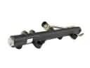 2007 Toyota Sequoia Fuel Rail
 2007 Toyota Sequoia Fuel Tank Strap
 2007 Toyota Sequoia Intake Manifold Gasket
 2007 Toyota Sequoia Throttle Body Gasket