×
ToyotaParts- Hello
- Login or Register
- Quick Links
- Live Chat
- Track Order
- Parts Availability
- RMA
- Help Center
- Contact Us
- Shop for
- Toyota Parts
- Scion Parts
My Garage
My Account
Cart
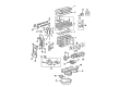
OEM 2007 Toyota RAV4 Timing Chain
Engine Timing Chain- Select Vehicle by Model
- Select Vehicle by VIN
Select Vehicle by Model
orMake
Model
Year
Select Vehicle by VIN
For the most accurate results, select vehicle by your VIN (Vehicle Identification Number).
4 Timing Chains found


2007 Toyota RAV4 Timing Chain
Part Number: 13507-0P010$73.58 MSRP: $103.28You Save: $29.70 (29%)Ships in 1-2 Business DaysProduct Specifications- Other Name: Chain Sub-Assembly; Engine Timing Chain; Secondary Chain
- Replaces: 13507-31020
- Part Name Code: 13507
- Item Weight: 1.40 Pounds
- Item Dimensions: 2.7 x 2.4 x 0.4 inches
- Condition: New
- Fitment Type: Direct Replacement
- Require Quantity: 2
- SKU: 13507-0P010
- Warranty: This genuine part is guaranteed by Toyota's factory warranty.


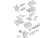
2007 Toyota RAV4 Timing Chain
Part Number: 13506-0H011$268.87 MSRP: $383.89You Save: $115.02 (30%)Ships in 1-2 Business DaysProduct Specifications- Other Name: Chain Sub-Assembly, Timing; Engine Timing Chain; Chain Sub-Assembly
- Replaces: 13506-28020, 13506-0H031, 13506-28010, 13506-28011, 13506-28021, 13506-0H010
- Part Name Code: 13506
- Item Weight: 1.20 Pounds
- Item Dimensions: 6.8 x 3.4 x 1.4 inches
- Condition: New
- Fitment Type: Direct Replacement
- SKU: 13506-0H011
- Warranty: This genuine part is guaranteed by Toyota's factory warranty.


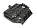
2007 Toyota RAV4 Timing Chain
Part Number: 13506-0P011$240.91 MSRP: $343.96You Save: $103.05 (30%)Ships in 1-2 Business DaysProduct Specifications- Other Name: Chain Sub-Assembly; Engine Timing Chain
- Manufacturer Note: (L)
- Replaces: 13506-31031, 13506-31020, 13506-0P010
- Part Name Code: 13506
- Item Weight: 1.40 Pounds
- Item Dimensions: 6.5 x 3.4 x 1.4 inches
- Condition: New
- Fitment Type: Direct Replacement
- SKU: 13506-0P011
- Warranty: This genuine part is guaranteed by Toyota's factory warranty.


2007 Toyota RAV4 Timing Chain
Part Number: 13507-28010$89.46 MSRP: $125.57You Save: $36.11 (29%)Ships in 1-2 Business DaysProduct Specifications- Other Name: Chain Sub-Assembly, Oil; Engine Timing Chain; Chain; Chain Sub-Assembly
- Replaces: 13507-0H020
- Part Name Code: 13507
- Item Weight: 0.70 Pounds
- Item Dimensions: 2.6 x 2.4 x 0.4 inches
- Condition: New
- Fitment Type: Direct Replacement
- SKU: 13507-28010
- Warranty: This genuine part is guaranteed by Toyota's factory warranty.
2007 Toyota RAV4 Timing Chain
Looking for affordable OEM 2007 Toyota RAV4 Timing Chain? Explore our comprehensive catalogue of genuine 2007 Toyota RAV4 Timing Chain. All our parts are covered by the manufacturer's warranty. Plus, our straightforward return policy and speedy delivery service ensure an unparalleled shopping experience. We look forward to your visit!
2007 Toyota RAV4 Timing Chain Parts Q&A
- Q: How to remove the timing chain on 2007 Toyota RAV4?A: Toward timing chain removal begin by disconnecting the battery cable from negative terminal then leaving it disconnected for at least 90 seconds until all Air Bag and pretensioner systems are deactivated. Begin the process by removing the radiator support opening cover and front wheel RH along with No. 1 engine under cover and front fender apron RH and No. 1 engine cover after unscrewing their 2 bolts. You must drain the engine oil before breaking off the front exhaust pipe along with the front suspension member reinforcement RH and the fan and generator V belt and generator assembly and the radiator reservoir by unbolting them. Disconnect the wire harness protector bolt and the two engine wire clamps to access the engine mounting insulator RH then use a transmission jack and remove the four bolts, two nuts and the insulator from the engine. First remove the engine mounting insulator FR following the same steps. After that detach the idler pulley through loosening its 2 bolts. The installation of the ignition coil assembly, spark plug and cylinder head cover sub-assembly requires disconnecting 2 ventilation hoses followed by removal of 2 bolts and 8 bolts and 2 nuts respectively. The oil pan sub-assembly removal process requires installing the No. 1 and No. 2 engine hangers with bolts before attaching a sling device and then removing 12 bolts and 2 nuts. Finally, use Special Service Tool: 09032-00100 to cut off the applied sealer and remove the oil pan while maintaining contact surface integrity. Manually position the cylinder number 1 to TDC functioning through crankshaft pulley alignment of timing mark "0" while examining camshaft timing gear and sprocket time indications. Special Service Tool 09213-54015 (91651-60855) and 09330-00021 should be used to remove the crankshaft pulley while Special Service Tool 09950-50013 (09951-05010, 09952-05010, 09953-05020, 09954-05021), 09950-40011 (09957-04010) might also be needed. Lift off the No. 1 chain tensioner assembly while removing the engine mounting bracket RH alongside V-ribbed belt tensioner assembly, crankshaft position sensor, and timing chain cover sub-assembly through proper bolt and nut uninstallation yet maintain contact surface integrity. Use proper procedures to remove the No. 1 crankshaft position sensor plate together with the timing chain guide, chain tensioner slipper, No. 1 chain vibration damper, chain sub-assembly, crankshaft timing sprocket, and No. 2 chain sub-assembly. An inspection of dimensional limitations should be conducted on the No. 1 chain tensioner as well as the chain sub-assembly and No. 2 chain sub-assembly and chain tensioner slipper and No. 1 chain vibration damper and crankshaft timing sprocket and oil pump drive sprocket and oil pump drive shaft sprocket using a vernier caliper. Replace any components that exceed the maximum specifications. Closing the operation requires use of Special Service Tool: 09223-22010 to install the new timing chain cover oil seal while both it and the timing gear case edge remain level. Before installation apply grease to the new seal.
Related 2007 Toyota RAV4 Parts
 2007 Toyota RAV4 Engine Cover
 2007 Toyota RAV4 Cylinder Head
 2007 Toyota RAV4 Crankshaft Seal
 2007 Toyota RAV4 Dipstick
 2007 Toyota RAV4 Exhaust Valve
 2007 Toyota RAV4 Harmonic Balancer
 2007 Toyota RAV4 Intake Valve
 2007 Toyota RAV4 Oil Pump Gasket
 2007 Toyota RAV4 Piston
 2007 Toyota RAV4 Rod Bearing
 2007 Toyota RAV4 Timing Cover
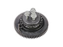 2007 Toyota RAV4 Timing Idler Gear