×
ToyotaParts- Hello
- Login or Register
- Quick Links
- Live Chat
- Track Order
- Parts Availability
- RMA
- Help Center
- Contact Us
- Shop for
- Toyota Parts
- Scion Parts
My Garage
My Account
Cart
OEM 2007 Toyota Highlander Wheel Hub
Wheel Axle Hub- Select Vehicle by Model
- Select Vehicle by VIN
Select Vehicle by Model
orMake
Model
Year
Select Vehicle by VIN
For the most accurate results, select vehicle by your VIN (Vehicle Identification Number).
5 Wheel Hubs found


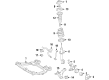
2007 Toyota Highlander Hub Assembly, Front
Part Number: 43502-0E030$130.65 MSRP: $184.95You Save: $54.30 (30%)Product Specifications- Other Name: Hub Sub-Assembly, Front Axle; Wheel Hub, Front; Front Hub & Bearing; Front Hub; Hub
- Position: Front
- Replaces: 43502-AA021, 43502-28100, 43502-08010, 43502-AA020
- Item Weight: 5.10 Pounds
- Item Dimensions: 6.6 x 6.9 x 4.6 inches
- Condition: New
- SKU: 43502-0E030
- Warranty: This genuine part is guaranteed by Toyota's factory warranty.


2007 Toyota Highlander Hub & Bearing Assembly, Rear Axle, Passenger Side
Part Number: 42410-0E050$333.29 MSRP: $475.87You Save: $142.58 (30%)Ships in 1-3 Business DaysProduct Specifications- Other Name: Hub&Bearing Assembly; Rear Axle, Driver Side; Wheel Hub Repair Kit; Wheel Bearing Kit; Axle Bearing
- Replaces: 42410-48041, 42410-0E021, 42410-48040
- Item Weight: 8.30 Pounds
- Item Dimensions: 6.9 x 6.9 x 4.6 inches
- Condition: New
- Fitment Type: Direct Replacement
- SKU: 42410-0E050
- Warranty: This genuine part is guaranteed by Toyota's factory warranty.


2007 Toyota Highlander Hub Assembly, Front
Part Number: 43502-28090$129.36 MSRP: $183.12You Save: $53.76 (30%)Ships in 1-3 Business DaysProduct Specifications- Other Name: Hub Sub-Assembly, Front Axle; Wheel Hub, Front; Front Hub; Hub; Hub Sub-Assembly, Front Axle, Passenger Side; Hub Sub-Assembly, Front Axle, Driver Side; Wheel Hub
- Manufacturer Note: (J)
- Position: Front
- Replaces: 43502-AA010, 43502-AA011
- Item Weight: 4.10 Pounds
- Item Dimensions: 6.7 x 6.7 x 4.5 inches
- Condition: New
- Fitment Type: Direct Replacement
- SKU: 43502-28090
- Warranty: This genuine part is guaranteed by Toyota's factory warranty.

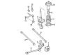
2007 Toyota Highlander Hub&Bearing Assembly, Rear Axle
Part Number: 42460-0E010$522.88 MSRP: $766.30You Save: $243.42 (32%)Ships in 1-3 Business DaysProduct Specifications- Other Name: HUB & BRG ASSY, RR A; Wheel Bearing and Hub Assembly; Wheel Hub Repair Kit; Wheel Bearing; Axle Bearing; Wheel Hub
- Position: Rear Driver Side
- Replaces: 42460-48030
- Item Weight: 9.90 Pounds
- Item Dimensions: 7.1 x 6.8 x 5.3 inches
- Condition: New
- SKU: 42460-0E010
- Warranty: This genuine part is guaranteed by Toyota's factory warranty.
2007 Toyota Highlander Hub&Bearing Assembly, Rear Axle
Part Number: 42450-0E010$522.88 MSRP: $766.30You Save: $243.42 (32%)Ships in 1-3 Business DaysProduct Specifications- Other Name: HUB & BRG ASSY, RR A; Wheel Bearing and Hub Assembly; Wheel Hub Repair Kit; Wheel Bearing; Axle Bearing; Wheel Hub
- Position: Rear Passenger Side
- Replaces: 42450-48030
- Item Weight: 10.00 Pounds
- Item Dimensions: 7.0 x 6.5 x 5.1 inches
- Condition: New
- SKU: 42450-0E010
- Warranty: This genuine part is guaranteed by Toyota's factory warranty.
2007 Toyota Highlander Wheel Hub
Looking for affordable OEM 2007 Toyota Highlander Wheel Hub? Explore our comprehensive catalogue of genuine 2007 Toyota Highlander Wheel Hub. All our parts are covered by the manufacturer's warranty. Plus, our straightforward return policy and speedy delivery service ensure an unparalleled shopping experience. We look forward to your visit!
2007 Toyota Highlander Wheel Hub Parts Q&A
- Q: How to service and repair the front Wheel Hub on 2007 Toyota Highlander?A: To service and repair front wheel hub, a loosiness and runout investigation on the on-vehicle. Take off the front wheel, disstake lock nut, and unscrew parts. Call of the front wheel hub sub-assembly and re-fit with special tools, taking care to correctly match the specifications in terms of torque on all connections. Lastly, fit front wheel and alignment and ABS sensor check.
Related 2007 Toyota Highlander Parts
 2007 Toyota Highlander Wheel Bearing
 2007 Toyota Highlander Backing Plate
 2007 Toyota Highlander Brake Caliper Bracket
 2007 Toyota Highlander Brake Disc
 2007 Toyota Highlander Brake Line
 2007 Toyota Highlander Brake Pad Set
 2007 Toyota Highlander Brake Shoe Set
 2007 Toyota Highlander Parking Brake Shoe
 2007 Toyota Highlander Spindle Nut
 2007 Toyota Highlander Wheel Cylinder
 2007 Toyota Highlander Wheel Stud
 2007 Toyota Highlander Yaw Sensor