×
ToyotaParts- Hello
- Login or Register
- Quick Links
- Live Chat
- Track Order
- Parts Availability
- RMA
- Help Center
- Contact Us
- Shop for
- Toyota Parts
- Scion Parts
My Garage
My Account
Cart
OEM 2007 Toyota Highlander Fuel Pressure Regulator
Fuel Tank Pressure Regulator- Select Vehicle by Model
- Select Vehicle by VIN
Select Vehicle by Model
orMake
Model
Year
Select Vehicle by VIN
For the most accurate results, select vehicle by your VIN (Vehicle Identification Number).
4 Fuel Pressure Regulators found


2007 Toyota Highlander Damper
Part Number: 23270-28021$190.00 MSRP: $271.28You Save: $81.28 (30%)Ships in 1-3 Business DaysProduct Specifications- Other Name: Damper Assembly, Fuel Pressure Pulsation; Fuel Pressure Damper
- Replaces: 23270-28020
- Part Name Code: 23270
- Item Weight: 1.40 Pounds
- Item Dimensions: 3.1 x 2.3 x 1.9 inches
- Condition: New
- Fitment Type: Direct Replacement
- SKU: 23270-28021
- Warranty: This genuine part is guaranteed by Toyota's factory warranty.


2007 Toyota Highlander Damper Set, Fuel Pressure Pulsation
Part Number: 23207-20011$93.01 MSRP: $130.55You Save: $37.54 (29%)Ships in 1-2 Business DaysProduct Specifications- Other Name: DAMPER SET, FUEL PRE; Fuel Pressure Damper; Fuel Pump Pulsator
- Replaces: 23207-46010, 23270-62010, 23270-62011, 23207-20010, 23207-74010
- Item Weight: 0.60 Pounds
- Item Dimensions: 3.0 x 2.2 x 2.0 inches
- Condition: New
- SKU: 23207-20011
- Warranty: This genuine part is guaranteed by Toyota's factory warranty.


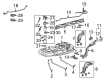
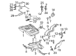
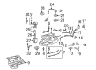
2007 Toyota Highlander Fuel Pressure Regulator
Part Number: 23280-20040$101.07 MSRP: $141.87You Save: $40.80 (29%)Ships in 1-3 Business DaysProduct Specifications- Other Name: Regulator Assembly, Fuel; Fuel Injection Pressure Regulator; Pressure Regulator; Regulator Assembly, Fuel Pressure
- Item Weight: 0.80 Pounds
- Item Dimensions: 4.8 x 4.0 x 2.7 inches
- Condition: New
- Fitment Type: Direct Replacement
- SKU: 23280-20040
- Warranty: This genuine part is guaranteed by Toyota's factory warranty.

2007 Toyota Highlander Fuel Pressure Regulator
Part Number: 23020-0A010$101.07 MSRP: $141.87You Save: $40.80 (29%)Ships in 1-3 Business DaysProduct Specifications- Other Name: Regulator Assembly, Fuel; Fuel Injection Pressure Regulator; Pressure Regulator; Regulator Assembly, Fuel Pressure
- Replaces: 23020-20010
- Part Name Code: 23280
- Item Weight: 0.80 Pounds
- Item Dimensions: 4.9 x 4.1 x 2.6 inches
- Condition: New
- Fitment Type: Direct Replacement
- SKU: 23020-0A010
- Warranty: This genuine part is guaranteed by Toyota's factory warranty.
2007 Toyota Highlander Fuel Pressure Regulator
Looking for affordable OEM 2007 Toyota Highlander Fuel Pressure Regulator? Explore our comprehensive catalogue of genuine 2007 Toyota Highlander Fuel Pressure Regulator. All our parts are covered by the manufacturer's warranty. Plus, our straightforward return policy and speedy delivery service ensure an unparalleled shopping experience. We look forward to your visit!
2007 Toyota Highlander Fuel Pressure Regulator Parts Q&A
- Q: How to service and repair the fuel pressure regulator on 2007 Toyota Highlander?A: Starting the fuel pressure regulator servicing process requires discharge of all fuel system pressure. Disassembly of the deck board sub-assembly begins with disconnecting the 5 retaining clips before rotatating the front aspect upward. The service and repair of the fuel pressure regulator requires removal of all seat track bracket cover outer items and both rear seat assemblies and the rear door scuff plate LH and the rear floor service hole cover. After this disconnect the fuel pump & sender gauge connector. Begin by disconnecting the fuel pump tube then take off the tube joint clip before pulling out the fuel pump tube while watching for dirt entry into the connector. You must use Special Service Tool 09808-14020 (09808-01410, 09808-01420, 09808-01430) to unfurl the fuel pump gauge retainer before removing it together with the fuel suction tube while being attentive to prevent damaging the fuel sender gauge arm. Start by taking off the gasket from the fuel tank then disconnect the fuel sender gauge connector followed by unlocking the gauge until it slides out. To extract the fuel suction plate through the 4 snap-claws while protecting it from damage and the fuel suction support No. 1. Use a wrench to disconnect the fuel pump connector after which you should remove the fuel pump by unclipping the two snap-claws without causing harm to either item. Extract the O-ring and fuel pump spacer during fuel pump removal. You must first pry the clip to access the fuel pump filter followed by disconnecting the fuel tube joint connector No. 1 before carefully pulling the joint from its position. Start by taking off the fuel pump harness from fuel tube joint No. 1 before removing the fuel pressure regulator assembly by unclipping it followed by removing two O-rings. First apply a thin layer of gasoline or spindle oil to both new O-rings then fit them to the fuel pressure regulator before installing the regulator onto the fuel tube joint No. 1 by reusing the clip for retention. Secure the fuel pump harness by placing a light oil coating onto a new O-ring before connecting it along with the fuel tube joint No. 1. The first step is to install the new fuel pump filter with its clip before adding a light oil coating on a new O-ring for the fuel pump spacer. Finally place the spacer with the O-ring onto the fuel suction plate then connect the fuel pump connector. A light coat of gasoline or spindle oil should be applied to a new O-ring for the fuel suction plate sub-assembly before installing it to the fuel suction support No. 1. Mount the fuel sender gauge assembly as well as the fuel suction tube assembly with pump and gauge and apply a new gasket to the fuel tank before you connect the fuel suction tube when the keyway finds proper alignment. Apply MP grease to the interior section of the fuel pump gauge retainer before following the triangle mark to the "S" mark on the fuel tank for attachment by turning the retainer one and a half times using Special Service Tool: 09808-14020 (09808-01410, 09808-01420, 09808-01430). Besides inspecting for scratch-free and debris-free conditions in the joint area the tube joint clip should be tightly installed. Conclude the procedure by verifying fuel leaks then installing fresh butyl tape to the rear floor service hole cover while connecting the fuel pump and sender gauge connector finally reattaching the rear floor service hole cover together with the rear door scuff plate LH followed by rear seat assemblies (both LH and RH) and the rear seat track bracket cover outer and the deck board sub-assembly.
Related 2007 Toyota Highlander Parts
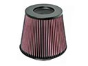 2007 Toyota Highlander Air Filter
 2007 Toyota Highlander Gas Cap
 2007 Toyota Highlander Fuel Filter
 2007 Toyota Highlander Fuel Injector
 2007 Toyota Highlander Fuel Tank
 2007 Toyota Highlander Fuel Filler Hose
 2007 Toyota Highlander Fuel Injector O-Ring
 2007 Toyota Highlander Fuel Pump Gasket
 2007 Toyota Highlander Fuel Pump Wiring Harness
 2007 Toyota Highlander Fuel Tank Lock Ring
 2007 Toyota Highlander Intake Manifold
 2007 Toyota Highlander Intake Manifold Gasket