×
ToyotaParts- Hello
- Login or Register
- Quick Links
- Live Chat
- Track Order
- Parts Availability
- RMA
- Help Center
- Contact Us
- Shop for
- Toyota Parts
- Scion Parts
My Garage
My Account
Cart
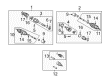
OEM 2007 Toyota Highlander Axle Shaft
Car Axle Shaft- Select Vehicle by Model
- Select Vehicle by VIN
Select Vehicle by Model
orMake
Model
Year
Select Vehicle by VIN
For the most accurate results, select vehicle by your VIN (Vehicle Identification Number).
13 Axle Shafts found


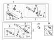
2007 Toyota Highlander Axle Assembly, Driver Side
Part Number: 43420-48091$370.57 MSRP: $543.06You Save: $172.49 (32%)Ships in 1-3 Business DaysProduct Specifications- Other Name: Shaft Assembly, Front Drive; CV Axle Assembly, Front Left; GSP Cv Axle; Axle Shaft; Shaft Assembly, Front Drive, Driver Side; CV Axle Assembly
- Position: Driver Side
- Replaces: 43420-48090
- Part Name Code: 43420
- Item Weight: 6.00 Pounds
- Item Dimensions: 8.7 x 4.6 x 4.3 inches
- Condition: New
- Fitment Type: Direct Replacement
- SKU: 43420-48091
- Warranty: This genuine part is guaranteed by Toyota's factory warranty.

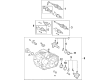
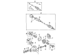
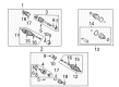
2007 Toyota Highlander Axle Assembly, Rear
Part Number: 42340-28091$333.41 MSRP: $476.04You Save: $142.63 (30%)Ships in 1-3 Business DaysProduct Specifications- Other Name: Shaft Assembly, Rear Drive; CV Axle Assembly, Rear Left, Rear Right; CV Axle Assembly; GSP Cv Axle; Axle Shaft
- Position: Rear
- Replaces: 42340-28090
- Item Weight: 12.20 Pounds
- Item Dimensions: 28.5 x 8.8 x 7.8 inches
- Condition: New
- SKU: 42340-28091
- Warranty: This genuine part is guaranteed by Toyota's factory warranty.

2007 Toyota Highlander Outer CV Joint, Driver Side
Part Number: 42370-49125$301.84 MSRP: $430.96You Save: $129.12 (30%)Ships in 1-3 Business DaysProduct Specifications- Other Name: Shaft Assembly, Rear Drive; CV Joint; Outer Joint; Shaft Assembly, Rear Drive Outboard Joint, Driver Side; Shaft Assembly, Rear Drive Outboard Joint
- Position: Driver Side
- Item Weight: 6.20 Pounds
- Item Dimensions: 8.7 x 4.5 x 4.1 inches
- Condition: New
- Fitment Type: Direct Replacement
- SKU: 42370-49125
- Warranty: This genuine part is guaranteed by Toyota's factory warranty.

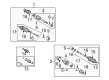
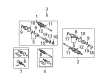
2007 Toyota Highlander Axle Shaft Assembly, Passenger Side
Part Number: 43410-48050$467.72 MSRP: $685.46You Save: $217.74 (32%)Ships in 1-3 Business DaysProduct Specifications- Other Name: Shaft Assembly, Front Drive; CV Axle Assembly, Front Right; GSP Cv Axle; Axle Shaft; Axle Assembly; Shaft Assembly, Front Drive, Passenger Side; CV Axle Assembly
- Position: Passenger Side
- Part Name Code: 43410
- Item Weight: 20.90 Pounds
- Item Dimensions: 43.7 x 5.9 x 5.6 inches
- Condition: New
- Fitment Type: Direct Replacement
- SKU: 43410-48050
- Warranty: This genuine part is guaranteed by Toyota's factory warranty.

2007 Toyota Highlander Axle Assembly, Passenger Side
Part Number: 43410-48061$424.82 MSRP: $622.58You Save: $197.76 (32%)Ships in 1-3 Business DaysProduct Specifications- Other Name: Shaft Assembly, Front Drive; CV Axle Assembly, Front Right; GSP Cv Axle; Axle Shaft; Shaft Assembly, Front Drive, Passenger Side; CV Axle Assembly
- Position: Passenger Side
- Replaces: 43410-48060
- Part Name Code: 43410
- Item Weight: 20.90 Pounds
- Item Dimensions: 44.6 x 5.9 x 5.5 inches
- Condition: New
- Fitment Type: Direct Replacement
- SKU: 43410-48061
- Warranty: This genuine part is guaranteed by Toyota's factory warranty.

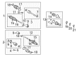
2007 Toyota Highlander Axle Assembly, Driver Side
Part Number: 43420-48100$420.85 MSRP: $616.76You Save: $195.91 (32%)Ships in 1-3 Business DaysProduct Specifications- Other Name: Shaft Assembly, Front Drive; CV Axle Assembly, Front Left; GSP Cv Axle; Axle Shaft; Shaft Assembly, Front Drive, Driver Side; CV Axle Assembly
- Position: Driver Side
- Part Name Code: 43420
- Item Weight: 17.90 Pounds
- Item Dimensions: 31.6 x 5.4 x 5.2 inches
- Condition: New
- Fitment Type: Direct Replacement
- SKU: 43420-48100
- Warranty: This genuine part is guaranteed by Toyota's factory warranty.

2007 Toyota Highlander Axle Assembly, Driver Side
Part Number: 43420-0W190$418.35 MSRP: $613.10You Save: $194.75 (32%)Ships in 1-3 Business DaysProduct Specifications- Other Name: Shaft Assembly, Front Drive; CV Axle Assembly, Front Left; GSP Cv Axle; Axle Shaft; Shaft Assembly, Front Drive, Driver Side; CV Axle Assembly
- Position: Driver Side
- Part Name Code: 43420
- Item Weight: 19.60 Pounds
- Item Dimensions: 31.9 x 5.4 x 5.4 inches
- Condition: New
- Fitment Type: Direct Replacement
- SKU: 43420-0W190
- Warranty: This genuine part is guaranteed by Toyota's factory warranty.

2007 Toyota Highlander Axle Assembly, Passenger Side
Part Number: 43410-48071$471.92 MSRP: $691.60You Save: $219.68 (32%)Ships in 1-3 Business DaysProduct Specifications- Other Name: Shaft Assembly, Front Drive; CV Axle Assembly, Front Right; GSP Cv Axle; Axle Shaft; Shaft Assembly, Front Drive, Passenger Side; CV Axle Assembly
- Position: Passenger Side
- Replaces: 43410-48070
- Part Name Code: 43410
- Item Weight: 14.40 Pounds
- Item Dimensions: 30.7 x 7.4 x 6.8 inches
- Condition: New
- Fitment Type: Direct Replacement
- SKU: 43410-48071
- Warranty: This genuine part is guaranteed by Toyota's factory warranty.

2007 Toyota Highlander Shaft Assembly, Front Drive, Driver Side
Part Number: 43420-0E021$468.29 MSRP: $686.28You Save: $217.99 (32%)Product Specifications- Other Name: Shaft Assembly, Front Drive; CV Axle Assembly; Axle Shaft
- Position: Driver Side
- Replaces: 43420-0E020
- Part Name Code: 43420
- Item Weight: 20.90 Pounds
- Item Dimensions: 28.9 x 6.3 x 6.3 inches
- Condition: New
- Fitment Type: Direct Replacement
- SKU: 43420-0E021
- Warranty: This genuine part is guaranteed by Toyota's factory warranty.

2007 Toyota Highlander Axle Shaft Assembly, Rear
Part Number: 42340-48030$380.89 MSRP: $558.21You Save: $177.32 (32%)Ships in 1-3 Business DaysProduct Specifications- Other Name: Shaft Assembly, Rear Drive; CV Axle Assembly, Rear Left, Rear Right; GSP Cv Axle; Axle Shaft; Axle Assembly; Shaft Assembly, Rear Drive, Passenger Side; Shaft Assembly, Rear Drive, Driver Side; CV Axle Assembly
- Position: Rear
- Item Weight: 5.90 Pounds
- Item Dimensions: 8.3 x 4.2 x 4.5 inches
- Condition: New
- Fitment Type: Direct Replacement
- SKU: 42340-48030
- Warranty: This genuine part is guaranteed by Toyota's factory warranty.

2007 Toyota Highlander Axle Shaft Assembly, Driver Side
Part Number: 43420-48061$370.57 MSRP: $543.06You Save: $172.49 (32%)Ships in 1-3 Business DaysProduct Specifications- Other Name: Shaft Assembly, Front Drive; CV Axle Assembly, Front Left; GSP Cv Axle; Axle Shaft; Axle Assembly; Shaft Assembly, Front Drive, Driver Side; CV Axle Assembly
- Position: Driver Side
- Replaces: 43420-48060
- Part Name Code: 43420
- Item Weight: 18.70 Pounds
- Item Dimensions: 31.0 x 5.4 x 5.4 inches
- Condition: New
- Fitment Type: Direct Replacement
- SKU: 43420-48061
- Warranty: This genuine part is guaranteed by Toyota's factory warranty.

2007 Toyota Highlander Axle Assembly, Passenger Side
Part Number: 43410-0W160$523.00 MSRP: $766.46You Save: $243.46 (32%)Product Specifications- Other Name: Shaft Assembly, Front Drive; CV Axle Assembly, Front Right; GSP Cv Axle; Axle Shaft; Shaft Assembly, Front Drive, Passenger Side; CV Axle Assembly
- Position: Passenger Side
- Part Name Code: 43410
- Item Weight: 25.80 Pounds
- Item Dimensions: 45.4 x 5.6 x 5.8 inches
- Condition: New
- Fitment Type: Direct Replacement
- SKU: 43410-0W160
- Warranty: This genuine part is guaranteed by Toyota's factory warranty.
 Product Specifications
- Other Name: Shaft Assembly, Front Drive; CV Axle Assembly, Front Right; GSP Cv Axle; Axle Shaft; Axle Assembly; Shaft Assembly, Front Drive, Passenger Side; CV Axle Assembly
- Position: Passenger Side
- Part Name Code: 43410
- Item Weight: 24.50 Pounds
- Item Dimensions: 43.7 x 5.5 x 5.5 inches
- Condition: New
- Fitment Type: Direct Replacement
- SKU: 43410-0W150
- Warranty: This genuine part is guaranteed by Toyota's factory warranty.
2007 Toyota Highlander Axle Shaft
Looking for affordable OEM 2007 Toyota Highlander Axle Shaft? Explore our comprehensive catalogue of genuine 2007 Toyota Highlander Axle Shaft. All our parts are covered by the manufacturer's warranty. Plus, our straightforward return policy and speedy delivery service ensure an unparalleled shopping experience. We look forward to your visit!
2007 Toyota Highlander Axle Shaft Parts Q&A
- Q: How to service and repair the axle shaft on 2007 Toyota Highlander?A: Your repair and servicing of the front drive shaft requires installation of new hole snap rings onto the front drive inner shaft inner LH and RH shafts specifically for 4WD models. The installation sequence requires vinyl tape on the drive shaft spline followed by placement of the outboard joint boot No. 2 clamp (A), then the outboard joint boot (B) and outboard joint boot clamp (C) in that order while applying grease to the outboard joint shaft and boot. Use SST 09521-24010 to pinch the outboard joint boot No. 2 clamp while holding the outboard joint shaft assembly between aluminum plates in a vise without forcing it tightly. Maintain 0.8 mm (0.031 inch) or less clearance in the clamp with SST 09240-00020. Use the same process of boot clamp installation for the outboard joint boot clamp. Position the drive shaft damper inside the shaft groove correctly then secure it with the drive shaft damper RH clamp through pinching the clamp using SST 09521-24010 while measuring the clearance with SST 09240-00020. New damaged clamps for the drive shaft damper RH must be installed using a screwdriver and needle-nose pliers. Attach inboard joint boot clamp (A) followed by inboard joint boot (B) and inboard joint boot No. 2 clamp (C) to the outboard joint shaft assembly being held in a vise. First align the beveled face of the tripod axial spline toward the outboard joint shaft while using a brass bar and hammer to tap in the tripod before installing a new front inner shaft snap ring using a snap ring expander. Also grease the inboard joint shaft and boot then set the matchmarks before installing the inboard joint assembly to the outboard joint shaft assembly. Use pliers to install the inboard joint boot after which a screwdriver will attach the inboard joint boot LH clamp. Check the front drive shaft assembly for any boot deterioration or unwanted movement throughout its components. When installing the inboard joint shaft assembly first apply ATF on its spline then line up the shaft splines before installing the drive shaft assembly with a brass bar while hammering it into position with the snap ring facing down. When installing a new bearing bracket hole snap ring on the front drive shaft assembly RH use a torque of 32 Nm (330 kgf-cm, 24 ft. lbs.). Install the drive shaft assembly LH onto the front axle assembly LH but do not allow damage to occur to the outboard joint boot or speed sensor rotor. Set the torque of the front suspension arm sub-assembly lower ball joint to 127 Nm (1,300 kgf-cm, 94 ft. lbs.) before connecting the tie rod end to the steering knuckle using torque of 49 Nm (500 kgf-cm, 36 ft. lbs.) while adding a new cotter pin. Use a torque wrench to install the speed sensor to the steering knuckle at 8.0 Nm but maintain a torque of 82 kgf-cm or 71 inch lbs. Next, wrap the speed sensor onto the shock absorber with a torque of 19 Nm while confirming no foreign debris sticks to the sensor. A hexagon (6 mm) wrench helps with stabilizer link assembly LH installation and requires 74 Nm (755 kgf-cm, 55 ft. lbs.) torque. Use a chisel to hammer stake the new axle hub LH nut meeting the torques of 294 Nm (3,000 kgf-cm, 217 ft. lbs.). When installing the front wheel apply 103 Nm (1,050 kgf-cm, 76 ft.lbs.) torque then proceed with adding automatic transaxle fluid, transfer oil for 4WD and inspecting front wheel alignment and verifying the ABS speed sensor signal.
Related 2007 Toyota Highlander Parts
 2007 Toyota Highlander Control Arm
 2007 Toyota Highlander CV Boot
 2007 Toyota Highlander CV Joint
 2007 Toyota Highlander Coil Springs
 2007 Toyota Highlander Differential Mount
 2007 Toyota Highlander Rear Crossmember
 2007 Toyota Highlander Sway Bar Bracket
 2007 Toyota Highlander Sway Bar Bushing
 2007 Toyota Highlander Sway Bar Kit
 2007 Toyota Highlander Trailing Arm
 2007 Toyota Highlander Transfer Case Output Shaft Snap Ring
 2007 Toyota Highlander Wheel Seal