×
ToyotaParts- Hello
- Login or Register
- Quick Links
- Live Chat
- Track Order
- Parts Availability
- RMA
- Help Center
- Contact Us
- Shop for
- Toyota Parts
- Scion Parts
My Garage
My Account
Cart
OEM 2007 Toyota FJ Cruiser Wheel Hub
Wheel Axle Hub- Select Vehicle by Model
- Select Vehicle by VIN
Select Vehicle by Model
orMake
Model
Year
Select Vehicle by VIN
For the most accurate results, select vehicle by your VIN (Vehicle Identification Number).
4 Wheel Hubs found


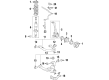
2007 Toyota FJ Cruiser Hub Assembly, Front
Part Number: 43502-60201$171.89 MSRP: $243.33You Save: $71.44 (30%)Ships in 1 Business DayProduct Specifications- Other Name: Hub Sub-Assembly, Front Axle; Wheel Hub, Front; Wheel Hub Repair Kit; Wheel Hub Assembly; Front Hub; Hub; Hub Sub-Assembly, Front Axle, Passenger Side; Hub Sub-Assembly, Front Axle, Driver Side; Wheel Hub
- Position: Front
- Replaces: 43502-60200, 43502-60180
- Item Weight: 1.40 Pounds
- Item Dimensions: 7.1 x 4.1 x 7.3 inches
- Condition: New
- Fitment Type: Direct Replacement
- SKU: 43502-60201
- Warranty: This genuine part is guaranteed by Toyota's factory warranty.


2007 Toyota FJ Cruiser Hub Assembly, Front
Part Number: 43502-35220$189.42 MSRP: $270.44You Save: $81.02 (30%)Ships in 1 Business DayProduct Specifications- Other Name: Hub Sub-Assembly, Front Axle; Wheel Hub, Front; Wheel Bear & Hub Assembly; Wheel Hub Repair Kit; Wheel Hub Module; Front Hub; Hub Sub-Assembly, Front Axle, Passenger Side; Hub Sub-Assembly, Front Axle, Driver Side; Wheel Hub
- Position: Front
- Replaces: 43502-35210
- Item Weight: 1.40 Pounds
- Item Dimensions: 6.9 x 6.4 x 4.7 inches
- Condition: New
- Fitment Type: Direct Replacement
- SKU: 43502-35220
- Warranty: This genuine part is guaranteed by Toyota's factory warranty.


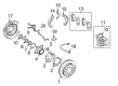
2007 Toyota FJ Cruiser Bearing Housing, Driver Side
Part Number: 42460-60010$344.80 MSRP: $505.32You Save: $160.52 (32%)Ships in 1-2 Business DaysProduct Specifications- Other Name: Bearing Assembly, Rear Axle; Wheel Bearing & Hub; Wheel Hub Repair Kit; Axle Bearing; Axle Bearings; Hub & Bearing; Hub & Bearing Assembly; Hub & Bearing Assembly, Rear Axle, Driver Side
- Position: Driver Side
- Replaces: 42460-60020
- Part Name Code: 42450B
- Item Weight: 2.80 Pounds
- Item Dimensions: 6.9 x 6.9 x 4.7 inches
- Condition: New
- Fitment Type: Direct Replacement
- SKU: 42460-60010
- Warranty: This genuine part is guaranteed by Toyota's factory warranty.

2007 Toyota FJ Cruiser Hub & Bearing Assembly, Rear Axle, Passenger Side
Part Number: 42450-60050$344.80 MSRP: $505.32You Save: $160.52 (32%)Ships in 1 Business DayProduct Specifications- Other Name: Bearing Assembly, Rear Axle; Wheel Bearing & Hub; Repair Kit; Axle Bearing
- Position: Passenger Side
- Replaces: 42450-60060
- Part Name Code: 42450A
- Item Weight: 6.10 Pounds
- Item Dimensions: 7.0 x 7.1 x 4.9 inches
- Condition: New
- Fitment Type: Direct Replacement
- SKU: 42450-60050
- Warranty: This genuine part is guaranteed by Toyota's factory warranty.
2007 Toyota FJ Cruiser Wheel Hub
Looking for affordable OEM 2007 Toyota FJ Cruiser Wheel Hub? Explore our comprehensive catalogue of genuine 2007 Toyota FJ Cruiser Wheel Hub. All our parts are covered by the manufacturer's warranty. Plus, our straightforward return policy and speedy delivery service ensure an unparalleled shopping experience. We look forward to your visit!
2007 Toyota FJ Cruiser Wheel Hub Parts Q&A
- Q: How to service and repair the front Wheel Hub on 2007 Toyota FJ Cruiser?A: The front axle hub will require loosening the negative battery terminal, unattaching the front wheel, empting the brake fluid to service the front wheel. Unscrew the brake caliper, speed sensor and axle hub. Take out and install seals and bearings with a special tool. Reassemble, with correct torque requirements, leak check, and check alignment.
Related 2007 Toyota FJ Cruiser Parts
 2007 Toyota FJ Cruiser Backing Plate
 2007 Toyota FJ Cruiser Brake Caliper
 2007 Toyota FJ Cruiser Brake Caliper Piston
 2007 Toyota FJ Cruiser Brake Disc
 2007 Toyota FJ Cruiser Brake Line
 2007 Toyota FJ Cruiser Hydraulic Hose
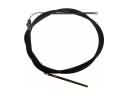 2007 Toyota FJ Cruiser Parking Brake Cable
 2007 Toyota FJ Cruiser Parking Brake Shoe
 2007 Toyota FJ Cruiser Speed Sensor
 2007 Toyota FJ Cruiser Wheel Cylinder
 2007 Toyota FJ Cruiser Wheel Cylinder Repair Kit
 2007 Toyota FJ Cruiser Wheel Stud