×
ToyotaParts- Hello
- Login or Register
- Quick Links
- Live Chat
- Track Order
- Parts Availability
- RMA
- Help Center
- Contact Us
- Shop for
- Toyota Parts
- Scion Parts
My Garage
My Account
Cart
OEM 2007 Toyota Camry Rack And Pinion
Steering Rack And Pinion- Select Vehicle by Model
- Select Vehicle by VIN
Select Vehicle by Model
orMake
Model
Year
Select Vehicle by VIN
For the most accurate results, select vehicle by your VIN (Vehicle Identification Number).
4 Rack And Pinions found


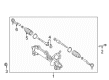
2007 Toyota Camry Steering Gear
Part Number: 44200-33472$718.56 MSRP: $1053.06You Save: $334.50 (32%)Ships in 1-3 Business DaysProduct Specifications- Other Name: Link Assembly, Electrical; Rack and Pinion Assembly; Steering Gearbox; EPS R/P; Gear Assembly; Link Assembly, Power Steering
- Replaces: 44200-33471, 44200-33470
- Part Name Code: 44200
- Item Weight: 21.60 Pounds
- Item Dimensions: 40.6 x 13.1 x 7.2 inches
- Condition: New
- Fitment Type: Direct Replacement
- SKU: 44200-33472
- Warranty: This genuine part is guaranteed by Toyota's factory warranty.


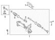
2007 Toyota Camry Steering Gear
Part Number: 44250-06330$653.07 MSRP: $957.08You Save: $304.01 (32%)Ships in 1-3 Business DaysProduct Specifications- Other Name: Gear Assembly, Power Steering; Rack and Pinion Assembly; Steering Gearbox; Rack & Pinion; Gear Assembly; Gear Assembly, Power Steering(For Rack & Pinion)
- Part Name Code: 44250
- Item Weight: 23.30 Pounds
- Item Dimensions: 51.2 x 10.8 x 6.7 inches
- Condition: New
- Fitment Type: Direct Replacement
- SKU: 44250-06330
- Warranty: This genuine part is guaranteed by Toyota's factory warranty.
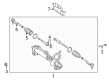
2007 Toyota Camry Steering Gear
Part Number: 44250-06340$653.07 MSRP: $957.08You Save: $304.01 (32%)Ships in 1-3 Business DaysProduct Specifications- Other Name: Gear Assembly, Power Steering; Rack and Pinion Assembly; Steering Gearbox; Rack & Pinion; Gear Assembly; Gear Assembly, Power Steering(For Rack & Pinion)
- Part Name Code: 44250
- Item Weight: 24.00 Pounds
- Item Dimensions: 49.7 x 10.5 x 6.7 inches
- Condition: New
- Fitment Type: Direct Replacement
- SKU: 44250-06340
- Warranty: This genuine part is guaranteed by Toyota's factory warranty.

2007 Toyota Camry Steering Gear
Part Number: 44200-33480$741.71 MSRP: $1086.99You Save: $345.28 (32%)Ships in 1-3 Business DaysProduct Specifications- Other Name: Link Assembly, Power Steering; Rack and Pinion Assembly; Steering Gearbox; Gear Assembly
- Part Name Code: 44200
- Item Weight: 22.20 Pounds
- Item Dimensions: 51.2 x 10.4 x 6.6 inches
- Condition: New
- Fitment Type: Direct Replacement
- SKU: 44200-33480
- Warranty: This genuine part is guaranteed by Toyota's factory warranty.
2007 Toyota Camry Rack And Pinion
Looking for affordable OEM 2007 Toyota Camry Rack And Pinion? Explore our comprehensive catalogue of genuine 2007 Toyota Camry Rack And Pinion. All our parts are covered by the manufacturer's warranty. Plus, our straightforward return policy and speedy delivery service ensure an unparalleled shopping experience. We look forward to your visit!
2007 Toyota Camry Rack And Pinion Parts Q&A
- Q: How to service and repair the Rack And Pinion on 2007 Toyota Camry?A: A proper power steering link service starts with wheel alignment in straight position followed by negative battery terminal disconnection. Insert the steering wheel into a seat-belt to stop rotation before removing the bolt that will allow the steering sliding yoke to glide aside from the power steering link assembly while marking each point for later reassembly. Separate the tie rod assembly LH by removing its cotter pin and nut while using Special Service Tool: 09628-00011 to detach it from the steering knuckle without damaging adjacent parts. The correct sequence should also be followed for removing the tie rod assembly on the right-hand side. Use the specified service tool: 09023-12701 to detach the pressure feed tube assembly from return and pressure feed tube sides and then remove the pressure feed tube clamp. Disassemble the power steering link assembly while unscrewing its bolts and nuts while avoiding 360-degree rotation of the nut. The power steering rack housing heat insulator should be removed during 2GR-FE model replacements. Use Special Service Tool 09612-00012 to restrain the power steering link assembly followed by the removal of steering left and right turn pressure tubes with their O-rings using Special Service Tool 09023-38201. Begin by removing all tie rod assemblies then continuing with steering rack boot clips, clamps and finally the No. 2 and No. 1 steering rack boots. Steering rack end subassemblies can be unstaked using Special Service Tool: 09922-10010 while removing the steering rack end subassemblies. Unscrew and disassemble the rack guide and dust cover in addition to the power steering control valve assembly by applying a socket wrench with 27 mm and Special Service Tool: 09616-00011. Utilize appropriate tools to remove the power steering control valve subassembly and all its components including lower and upper oil seals as well as spacers and top and bottom fittings. Different wrenches are needed to remove the cylinder end stopper hole snap ring along with power steering rack subassembly before proceeding to the cylinder end stopper and bushing removal. Prior to this step you should remove the O-ring together with the rack bushing oil seal using Special Service Tool: 09527-21011. The power steering rack should be inspected for runout and wear as well as the tie rod assemblies must be checked for their proper torque setting. Please check the total preload of installed steering rack ends before installation while making sure that the value stays under the specified measurement. Before assembly you should grease the specified parts according to power steering fluid requirements while using Special Service Tool: 09950-70010 to install the power piston oil seal and cylinder tube oil seal. The power steering rack subassembly bushing and cylinder end stopper should be installed after which assembly can proceed. The last step involves installing the cylinder end stopper hole snap ring while conducting air tightness testing with Special Service Tool: 09631-12071 and evaluating vacuum pressure stability.
Related 2007 Toyota Camry Parts
 2007 Toyota Camry Steering Wheel
 2007 Toyota Camry Power Steering Pump
 2007 Toyota Camry Power Steering Hose
 2007 Toyota Camry Power Steering Reservoir
 2007 Toyota Camry Steering Angle Sensor
 2007 Toyota Camry Steering Column
 2007 Toyota Camry Steering Shaft
 2007 Toyota Camry Tie Rod End
 2007 Toyota Camry Drag Link
 2007 Toyota Camry Shift Interlock Solenoid
 2007 Toyota Camry Steering Column Cover
 2007 Toyota Camry Steering Gear Box