My Garage
Cart

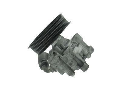
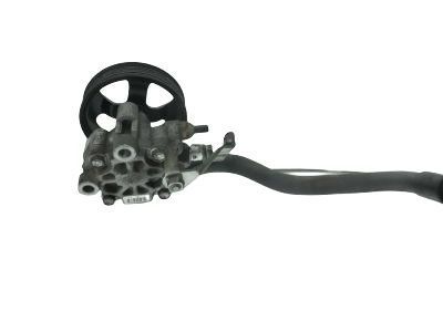
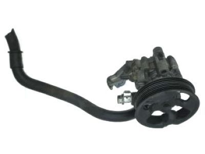
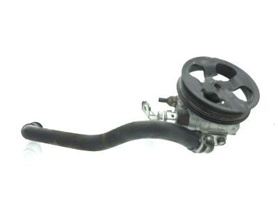
OEM 2007 Scion tC Power Steering Pump

Power Steering Pump Unit
  • Select Vehicle by Model
  • Select Vehicle by VIN
Select Vehicle by Model
Make
Model
Year
or
Select Vehicle by VIN
For the most accurate results, select vehicle by your VIN (Vehicle Identification Number).

1 Power Steering Pump found

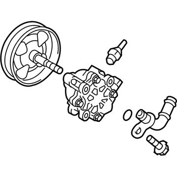
  • 2007 Scion tC Power Steering Pump Diagram - 44310-21050
    View related parts

    2007 Scion tC Power Steering Pump

    Part Number: 44310-21050
    $362.39 MSRP: $531.10
    You Save: $168.71 (32%)
    Ships in 1-3 Business Days
    ADD TO CART
    Product Specifications
    • Other Name: Pump Assembly, Vane; Pump
    • Part Name Code: 44320
    • Item Weight: 4.10 Pounds
    • Item Dimensions: 8.0 x 5.9 x 5.9 inches
    • Condition: New
    • Fitment Type: Direct Replacement
    • SKU: 44310-21050
    • Warranty: This genuine part is guaranteed by Toyota's factory warranty.
    More Info
    Fits the following 2007 Scion tC Submodels:
    • Base, Spec | 4 Cyl 2.4 L GAS

2007 Scion tC Power Steering Pump

Looking for affordable OEM 2007 Scion tC Power Steering Pump? Explore our comprehensive catalogue of genuine 2007 Scion tC Power Steering Pump. All our parts are covered by the manufacturer's warranty. Plus, our straightforward return policy and speedy delivery service ensure an unparalleled shopping experience. We look forward to your visit!

2007 Scion tC Power Steering Pump Parts Q&A

  • Q: How to service and repair the power steering pump on 2007 Scion tC?
    A: Your first action in servicing or repairing the power steering pump should involve removing the RH front wheel followed by drain pumping the power steering fluid then removing the front fender apron seal RH. Start by extracting the fan and generator V belt before unclipping the No. 1 oil reservoir to pump hose. It is essential to take care when working with the V belt to avoid fluid leakage. The pressure feed tube assembly can be detached through the removal of its bolt and subsequent disconnection from the pump bracket rear while using a 27 mm wrench to maintain pressure port union stability during screw and gasket removal. The vane pump assembly removal begins by disconnecting the oil pressure switch connector followed by using SST 09249-63010 to loosen the 2 bolts which will enable removal of the vane pump. Fix the vane pump assembly inside an SST 09630-00014 (09631-00132) vise prior to removing the rear vane pump bracket and power steering suction union port bolt with O-ring. After removal of the flow control valve and pressure port union and its O-ring the power steering oil pressure switch should be replaced if found damaged. Access the rear vane pump housing by unfastening its 4 bolts and O-ring before you disassemble the shaft sub-assembly with pulley by applying 2 screwdrivers to remove the snap ring. The technician should commence the disassembly by taking out the vane pump rotor and the 10 vane pump plates together with the vane pump cam ring and front vane pump side plate where all components require O-ring removal. The removal of the vane pump housing oil seal requires special care because it may damage the front housing structure. A professional should check the oil clearance between vane pump shaft and bush in housing front by measuring to prevent excess clearance of 0.07 mm (0.0028 inch). The thickness measurement of vane pump plates should fall within the range of 1.405 to 1.411 mm (0.05531 to 0.05555 inch) while maintaining a clearance check between vane pump rotor groove and vane plates under 0.03 mm (0.0012 inch). Check the flow control valve for proper operation and leakage while measuring its compression spring free length to be at minimum 36.9 mm (1.453 inch). The vane pump assembly requires replacement when additional specifications or damage signs appear in any component. To install the new oil seal apply power steering fluid onto its lips before insertion with SST 09950-60010 (09951-00280) or 09950-70010 (09951-07100) while maintaining the precise installation direction. Put the pulley shaft inside slowly while checking for damage to the oil seal lip before placing the front vane pump side plate with O-rings correctly positioned. Enable vane pump cam ring installation by placing its inscribed mark at the top before inserting vane pump rotor and plates where round ends must face outward. Place a new snap ring on the shaft before applying power steering fluid to a fresh O-ring which you will install onto the rear housing after positioning it correctly then applying four bolts with 22 Nm (224 kgf-cm, 16 ft. lbs. of torque. The service bolt installation should proceed after ensuring the pump operates without resistance while measuring the pulley rotating torque where 0.27 Nm (2.8 kgf-cm, 2.4 ft. lbs.) represents an acceptable reading criterion. When mounting the power steering oil pressure switch it should have 21 Nm torque (214 kgf-cm, 15 ft. lbs.) and flow control valve plus compression spring must follow with power steering fluid application before final installation. Mount the pressure port union by applying 69 Nm torque to the new O-ring before securing the rear vane pump bracket at 37 Nm to allow the stopper to contact the body of the pump. The power steering suction port union gets installed using a new O-ring at 12 Nm of torque (122 kgf-cm, 9 ft. lbs.) before the vane pump assembly goes in and the bolts should be tightened at 34 Nm (347 kgf-cm, 25 ft. lbs.) using tool SST 09249-63010. Carefully connect the pressure feed tube assembly and the No. 1 oil reservoir for the pump hose tubing before reinstalling the fan and generator V belt and the front fender apron seal RH along with the front wheel RH. Perform a fluid bleed on power steering then investigate for any fluid leakage.