×
ToyotaParts- Hello
- Login or Register
- Quick Links
- Live Chat
- Track Order
- Parts Availability
- RMA
- Help Center
- Contact Us
- Shop for
- Toyota Parts
- Scion Parts
My Garage
My Account
Cart
OEM 2006 Toyota Tundra Brake Proportioning Valve
Proportioning Valve- Select Vehicle by Model
- Select Vehicle by VIN
Select Vehicle by Model
orMake
Model
Year
Select Vehicle by VIN
For the most accurate results, select vehicle by your VIN (Vehicle Identification Number).
1 Brake Proportioning Valve found


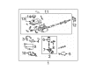
2006 Toyota Tundra Load Proportioning Valve
Part Number: 47910-34070$262.23 MSRP: $374.40You Save: $112.17 (30%)Ships in 1-2 Business DaysProduct Specifications- Other Name: Valve Assembly, Load Sensing With Spring; Brake Proportioning Valve; Valve Assembly, Load Sensing Proportioning
- Manufacturer Note: W(ABS)
- Part Name Code: 47910
- Item Weight: 1.60 Pounds
- Item Dimensions: 4.1 x 3.4 x 2.2 inches
- Condition: New
- Fitment Type: Direct Replacement
- SKU: 47910-34070
- Warranty: This genuine part is guaranteed by Toyota's factory warranty.
2006 Toyota Tundra Brake Proportioning Valve
Looking for affordable OEM 2006 Toyota Tundra Brake Proportioning Valve? Explore our comprehensive catalogue of genuine 2006 Toyota Tundra Brake Proportioning Valve. All our parts are covered by the manufacturer's warranty. Plus, our straightforward return policy and speedy delivery service ensure an unparalleled shopping experience. We look forward to your visit!
2006 Toyota Tundra Brake Proportioning Valve Parts Q&A
- Q: How to service and repair the Brake Proportioning Valve on 2006 Toyota Tundra?A: Service and repair of the Brake Proportioning/Combination Valve begins with removing the valve bracket through its nut, washer, bolt and plate washers followed by the 2 nuts and 2 washers and set plate and valve bracket from the valve body. The valve spring can be disconnected through plier usage which removes the clip then the spring. Disconnect shackle No.1 and shackle No.2 by taking off the nut washer and bolt together with the load sensing spring and 2 plate washers and then lightly loosen the 2 nuts and plate washer plate to separate shackle No.1 from shackle No.2 The load sensing spring disassembly requires removal of 4 bushings and 2 collars in sequence followed by uninstallation of the load sensing valve boot and load sensing spring boot. Check the valve piston pin along with the load sensing contact surface for wear until it reaches 0.7 mm (0.028 inch) beyond the allowed maximum limit. When reconnecting the system install the load sensing valve boot and load sensing spring boot before placing the 2 collars followed by the 4 bushings while applying lithium soap-base glycol grease to all contact areas and aligning the load sensing spring correctly. First bolt shackle No.1 to shackle No.2 by fastening the lock nut and plate washer between the shackle components then tighten the upper nut to 13 Nm (130 kgf-cm, 9 ft. lbs.). The spring of the load sensing assembly should have 2 plate washers applied before the bolt installation, washer, and finally the nut which should be tightened to 18 Nm (185 kgf-cm, 13 ft. lbs.). Screw the load sensing spring into the load sensing valve using the clip before you install the valve bracket by establishing the set plate between the valve bracket and load sensing valve and then tighten the 2 washers and 2 nuts as a temporary step before installing the load sensing spring assembly followed by 2 plate washers bolt washer nut that should be torqued to 18 Nm (185 kgf-cm, 13 ft. lbs.).
Related 2006 Toyota Tundra Parts
 2006 Toyota Tundra Brake Caliper
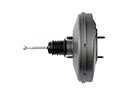 2006 Toyota Tundra Brake Booster
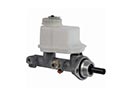 2006 Toyota Tundra Brake Master Cylinder
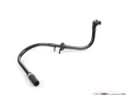 2006 Toyota Tundra Brake Booster Vacuum Hose
 2006 Toyota Tundra Brake Caliper Piston
 2006 Toyota Tundra Brake Fluid Pump
 2006 Toyota Tundra Brake Line
 2006 Toyota Tundra Brake Master Cylinder Reservoir
 2006 Toyota Tundra Brake Pad Set
 2006 Toyota Tundra Hydraulic Hose
 2006 Toyota Tundra Master Cylinder Repair Kit
 2006 Toyota Tundra Wheel Cylinder Repair Kit