×
ToyotaParts- Hello
- Login or Register
- Quick Links
- Live Chat
- Track Order
- Parts Availability
- RMA
- Help Center
- Contact Us
- Shop for
- Toyota Parts
- Scion Parts
My Garage
My Account
Cart
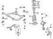
OEM 2006 Toyota Solara Control Arm
Suspension Arm- Select Vehicle by Model
- Select Vehicle by VIN
Select Vehicle by Model
orMake
Model
Year
Select Vehicle by VIN
For the most accurate results, select vehicle by your VIN (Vehicle Identification Number).
2 Control Arms found


2006 Toyota Solara Control Arm, Lower Driver Side
Part Number: 48069-06100$169.42 MSRP: $239.84You Save: $70.42 (30%)Ships in 1 Business DayProduct Specifications- Other Name: Arm Sub-Assembly, Suspension; Suspension Control Arm, Front Left; Control Arm Assembly; Lower Control Arm; Arm Sub-Assembly, Front Suspension, Lower Driver Side; Suspension Control Arm
- Position: Lower Driver Side
- Replaces: 48069-58010, 48069-28120
- Part Name Code: 48069
- Item Weight: 10.60 Pounds
- Item Dimensions: 2.9 x 2.9 x 2.8 inches
- Condition: New
- Fitment Type: Direct Replacement
- SKU: 48069-06100
- Warranty: This genuine part is guaranteed by Toyota's factory warranty.

2006 Toyota Solara Control Arm, Passenger Side
Part Number: 48068-06100$161.79 MSRP: $229.03You Save: $67.24 (30%)Ships in 1 Business DayProduct Specifications- Other Name: Arm Sub-Assembly, Suspension; Suspension Control Arm, Front Right; Control Arm Assembly; Lower Control Arm; Arm Sub-Assembly, Front Suspension, Lower Passenger Side; Suspension Control Arm
- Position: Passenger Side
- Replaces: 48068-28120, 48068-58010
- Part Name Code: 48068
- Item Weight: 7.80 Pounds
- Item Dimensions: 18.2 x 2.8 x 15.4 inches
- Condition: New
- Fitment Type: Direct Replacement
- SKU: 48068-06100
- Warranty: This genuine part is guaranteed by Toyota's factory warranty.
2006 Toyota Solara Control Arm
Looking for affordable OEM 2006 Toyota Solara Control Arm? Explore our comprehensive catalogue of genuine 2006 Toyota Solara Control Arm. All our parts are covered by the manufacturer's warranty. Plus, our straightforward return policy and speedy delivery service ensure an unparalleled shopping experience. We look forward to your visit!
2006 Toyota Solara Control Arm Parts Q&A
- Q: How to service and repair the rear No.2 lower Control Arm on 2006 Toyota Solara?A: The repair and servicing of the rear No.2 lower suspension arm requires first removing the rear wheel followed by the center exhaust pipe assembly, stabilizer bar rear, and separating the rear strut rod assembly and both No.1 and No.2 rear suspension arm assemblies left and right. The rear suspension arm No.2 requires disconnection through bolt removal on its inner side after subassembly removal of the rear suspension member. Begin installation of the No.2 rear suspension arm assembly LH by orienting it with the paint mark on the rear side of the vehicle. Then fasten the bolt with just enough force to achieve 100 Nm (1,020 kgf-cm, 74 ft. lbs.) of torque. The next step involves installing the rear suspension member subassembly while temporarily tightening all three components including both No.1 and No.2 rear suspension arm assemblies LH and RH as well as the rear strut rod assembly. After stabilizing the suspension apply full torque to all No.1 and No.2 rear suspension arm assemblies LH and RH and rear strut rod assembly. The stabilizer bar rear, center exhaust pipe assembly and rear wheel should be installed now along with proper wheel torque maintenance of 103 Nm (1,050 kgf-cm, 76 ft. lbs.) while verifying the rear wheel alignment.
Related 2006 Toyota Solara Parts
 2006 Toyota Solara Ball Joint
 2006 Toyota Solara Bump Stop
 2006 Toyota Solara Coil Spring Insulator
 2006 Toyota Solara Coil Springs
 2006 Toyota Solara Lateral Link
 2006 Toyota Solara Rear Crossmember
 2006 Toyota Solara Shock Absorber
 2006 Toyota Solara Shock And Strut Mount
 2006 Toyota Solara Steering Knuckle
 2006 Toyota Solara Strut Housing
 2006 Toyota Solara Sway Bar Bracket
 2006 Toyota Solara Sway Bar Bushing