×
ToyotaParts- Hello
- Login or Register
- Quick Links
- Live Chat
- Track Order
- Parts Availability
- RMA
- Help Center
- Contact Us
- Shop for
- Toyota Parts
- Scion Parts
My Garage
My Account
Cart
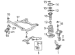
OEM 2006 Toyota Solara Ball Joint
Control Arm Joint- Select Vehicle by Model
- Select Vehicle by VIN
Select Vehicle by Model
orMake
Model
Year
Select Vehicle by VIN
For the most accurate results, select vehicle by your VIN (Vehicle Identification Number).
2 Ball Joints found


2006 Toyota Solara Joint Assembly, Lower Ball, Front Passenger Side
Part Number: 43330-09560$71.09 MSRP: $99.79You Save: $28.70 (29%)Ships in 1-3 Business DaysProduct Specifications- Other Name: Joint Set, Lower Ball; Suspension Ball Joint; Ball Joint
- Position: Front Passenger Side
- Replaces: 43330-09160
- Part Name Code: 43330K
- Item Weight: 2.20 Pounds
- Item Dimensions: 5.6 x 3.6 x 2.6 inches
- Condition: New
- Fitment Type: Direct Replacement
- SKU: 43330-09560
- Warranty: This genuine part is guaranteed by Toyota's factory warranty.

2006 Toyota Solara Ball Joint, Front Driver Side
Part Number: 43340-09010$65.52 MSRP: $91.97You Save: $26.45 (29%)Ships in 1-3 Business DaysProduct Specifications- Other Name: Joint Assembly, Lower Ball; Suspension Ball Joint, Front Left; Lower Ball Joint; Joint Assembly, Lower Ball, Front Driver Side; Suspension Ball Joint
- Position: Front Driver Side
- Replaces: 43340-09080
- Part Name Code: 43340A
- Item Weight: 1.50 Pounds
- Item Dimensions: 5.6 x 3.4 x 2.6 inches
- Condition: New
- Fitment Type: Direct Replacement
- SKU: 43340-09010
- Warranty: This genuine part is guaranteed by Toyota's factory warranty.
2006 Toyota Solara Ball Joint
Looking for affordable OEM 2006 Toyota Solara Ball Joint? Explore our comprehensive catalogue of genuine 2006 Toyota Solara Ball Joint. All our parts are covered by the manufacturer's warranty. Plus, our straightforward return policy and speedy delivery service ensure an unparalleled shopping experience. We look forward to your visit!
2006 Toyota Solara Ball Joint Parts Q&A
- Q: How to service and repair the front lower ball joint on 2006 Toyota Solara?A: The repair process for front lower ball joints requires beginning by removing the front wheel and the front axle hub LH nut followed by disconnecting speed sensor front LH and the front disc brake caliper assembly LH and front disc and tie rod assembly LH and front suspension No.1 lower arm sub-assembly LH. Proceed with standard procedure by taking out the cotter pin and castle nut of the front axle assembly LH and front lower ball joint assembly. Then apply Special Service Tool: 09628-62011 to extract the lower ball joint assembly front LH. Secure the lower ball joint assembly front LH in a vise before installing the nut to the stud bolt and flipping the ball joint several times between the fifth and more times total. Leaning on a torque wrench set to rotate the nut at 3 to 5 seconds for each turn enables serial torque measurements; halt the process while the fifth turn reaches 0.98 to 3.43 Nm (10 to 35 kgf-cm, 8.7 to 30 ft. lbs.). Deviations from these readings warrant replacing the lower ball joint assembly. The installation process requires the lower ball joint assembly front LH attached to the steering knuckle using a castle nut at 123 Nm (1,250 kgf-cm, 91 ft. lbs.) torque then the nut can be tightened further to up to 60 degrees if the cotter pin holes are in the wrong position. The installation sequence begins with a new cotter pin then the front axle assembly LH followed by the front suspension No.1 lower arm sub-assembly after which the tie rod assembly LH the front disc and the front disc brake caliper assembly LH and speed sensor front LH until the front axle hub LH nut reaches 103 Nm (1,050 kgf-cm, 76 ft. lbs. torque). The inspection of front wheel alignment and ABS speed sensor signal testing occurs after both VSC and without VSC activation.
Related 2006 Toyota Solara Parts
 2006 Toyota Solara Bump Stop
 2006 Toyota Solara Coil Spring Insulator
 2006 Toyota Solara Coil Springs
 2006 Toyota Solara Control Arm
 2006 Toyota Solara Front Cross-Member
 2006 Toyota Solara Shock Absorber
 2006 Toyota Solara Shock And Strut Mount
 2006 Toyota Solara Steering Knuckle
 2006 Toyota Solara Strut Housing
 2006 Toyota Solara Sway Bar Bracket
 2006 Toyota Solara Sway Bar Bushing
 2006 Toyota Solara Sway Bar Kit