×
ToyotaParts- Hello
- Login or Register
- Quick Links
- Live Chat
- Track Order
- Parts Availability
- RMA
- Help Center
- Contact Us
- Shop for
- Toyota Parts
- Scion Parts
My Garage
My Account
Cart
OEM 2006 Toyota Land Cruiser Cooling Fan Assembly
Engine Cooling Fan- Select Vehicle by Model
- Select Vehicle by VIN
Select Vehicle by Model
orMake
Model
Year
Select Vehicle by VIN
For the most accurate results, select vehicle by your VIN (Vehicle Identification Number).
1 Cooling Fan Assembly found


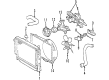
2006 Toyota Land Cruiser Fan Blade
Part Number: 16361-50170$160.26 MSRP: $226.86You Save: $66.60 (30%)Ships in 1-3 Business DaysProduct Specifications- Other Name: Fan; Engine Cooling Fan Clutch Blade; Radiator Fan Assembly
- Part Name Code: 16361
- Item Weight: 1.80 Pounds
- Item Dimensions: 13.3 x 12.6 x 3.9 inches
- Condition: New
- Fitment Type: Direct Replacement
- SKU: 16361-50170
- Warranty: This genuine part is guaranteed by Toyota's factory warranty.
2006 Toyota Land Cruiser Cooling Fan Assembly
Looking for affordable OEM 2006 Toyota Land Cruiser Cooling Fan Assembly? Explore our comprehensive catalogue of genuine 2006 Toyota Land Cruiser Cooling Fan Assembly. All our parts are covered by the manufacturer's warranty. Plus, our straightforward return policy and speedy delivery service ensure an unparalleled shopping experience. We look forward to your visit!
2006 Toyota Land Cruiser Cooling Fan Assembly Parts Q&A
- Q: How to service and repair the Cooling Fan Assembly on 2006 Toyota Land Cruiser?A: To maintain radiator cooling fan, it is important to disconnect the negative battery, take off the engine under cover, empty fluids, and remove the radiator hose and radiator reservoir. Take off fan assembly and check against damage and replace parts, with correct torque requirements. Lastly, re-connect the battery, verify whether there are any leaks and replace the under cover.
Related 2006 Toyota Land Cruiser Parts
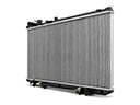 2006 Toyota Land Cruiser Radiator
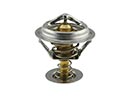 2006 Toyota Land Cruiser Thermostat
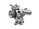 2006 Toyota Land Cruiser Water Pump
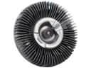 2006 Toyota Land Cruiser Fan Clutch
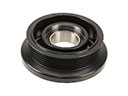 2006 Toyota Land Cruiser A/C Idler Pulley
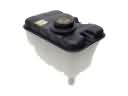 2006 Toyota Land Cruiser Coolant Reservoir
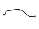 2006 Toyota Land Cruiser Coolant Reservoir Hose
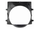 2006 Toyota Land Cruiser Fan Shroud
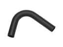 2006 Toyota Land Cruiser Radiator Hose
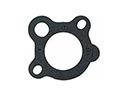 2006 Toyota Land Cruiser Thermostat Gasket
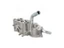 2006 Toyota Land Cruiser Thermostat Housing
 2006 Toyota Land Cruiser Water Pump Gasket