×
ToyotaParts- Hello
- Login or Register
- Quick Links
- Live Chat
- Track Order
- Parts Availability
- RMA
- Help Center
- Contact Us
- Shop for
- Toyota Parts
- Scion Parts
My Garage
My Account
Cart
OEM 2006 Toyota Avalon Camshaft
Cam- Select Vehicle by Model
- Select Vehicle by VIN
Select Vehicle by Model
orMake
Model
Year
Select Vehicle by VIN
For the most accurate results, select vehicle by your VIN (Vehicle Identification Number).
4 Camshafts found

2006 Toyota Avalon Camshaft
Part Number: 13502-31061$533.55 MSRP: $781.93You Save: $248.38 (32%)Ships in 1-3 Business DaysProduct Specifications- Other Name: Camshaft Sub-Assembly
- Replaces: 13502-31041, 13502-0P020, 13502-31040, 13502-31060, 13502-31080, 13502-0P021
- Part Name Code: 13512
- Item Weight: 4.40 Pounds
- Item Dimensions: 20.7 x 3.3 x 2.8 inches
- Condition: New
- Fitment Type: Direct Replacement
- SKU: 13502-31061
- Warranty: This genuine part is guaranteed by Toyota's factory warranty.

2006 Toyota Avalon Camshaft
Part Number: 13501-31091$533.55 MSRP: $781.93You Save: $248.38 (32%)Ships in 1-3 Business DaysProduct Specifications- Other Name: Camshaft Sub-Assembly
- Replaces: 13501-31100, 13501-31090, 13501-0P021, 13501-0P020, 13501-31061, 13501-31060
- Part Name Code: 13511
- Item Weight: 4.60 Pounds
- Item Dimensions: 21.5 x 3.5 x 3.0 inches
- Condition: New
- Fitment Type: Direct Replacement
- SKU: 13501-31091
- Warranty: This genuine part is guaranteed by Toyota's factory warranty.

2006 Toyota Avalon Camshaft Sub-Assembly
Part Number: 13054-31061$533.55 MSRP: $781.93You Save: $248.38 (32%)Ships in 1-3 Business DaysProduct Specifications- Other Name: Camshaft
- Replaces: 13054-0P020, 13054-31030, 13054-31080, 13054-31060, 13054-0P021, 13054-31031
- Part Name Code: 13054
- Item Weight: 4.80 Pounds
- Item Dimensions: 21.8 x 3.4 x 2.9 inches
- Condition: New
- Fitment Type: Direct Replacement
- SKU: 13054-31061
- Warranty: This genuine part is guaranteed by Toyota's factory warranty.

2006 Toyota Avalon Camshaft
Part Number: 13053-31061$533.55 MSRP: $781.93You Save: $248.38 (32%)Ships in 1-3 Business DaysProduct Specifications- Other Name: Camshaft Sub-Assembly
- Replaces: 13053-0P021, 13053-31080, 13053-0P020, 13053-31060
- Part Name Code: 13053
- Item Weight: 4.80 Pounds
- Item Dimensions: 21.4 x 3.6 x 3.0 inches
- Condition: New
- Fitment Type: Direct Replacement
- SKU: 13053-31061
- Warranty: This genuine part is guaranteed by Toyota's factory warranty.
2006 Toyota Avalon Camshaft
Looking for affordable OEM 2006 Toyota Avalon Camshaft? Explore our comprehensive catalogue of genuine 2006 Toyota Avalon Camshaft. All our parts are covered by the manufacturer's warranty. Plus, our straightforward return policy and speedy delivery service ensure an unparalleled shopping experience. We look forward to your visit!
2006 Toyota Avalon Camshaft Parts Q&A
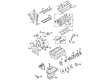
- Q: How to service the camshaft on the RH bank on 2006 Toyota Avalon?A: The repair of the RH bank camshaft on the 2GR-FE engine starts with removing the engine assembly that includes transaxle and engine wire with front frame assembly and starter assembly along with automatic transaxle assembly and oil level gauge guide sub-assembly and exhaust manifold sub-assemblies (RH and LH) and drive plate & ring gear sub-assembly and idler pulley sub-assembly No.2. Extract the engine mounting bracket RH alongside the water pump pulley, V-ribbed belt tensioner assembly, timing gear cover No.2, engine mounting stay No.2 RH, engine mounting bracket front No.1 LH, water inlet housing, crankshaft pulley, oil pan sub-assemblies (No.2 and the main), oil strainer sub-assembly, intake air surge tank, ignition coil assembly, and oil pipes No.1 and No.2 while removing all corresponding unions and filters. The technician must separate the cylinder head cover sub-assemblies (both RH and LH), timing chain cover sub-assembly and timing chain cover oil seal from the unit. Proceed with the steps by positioning the No.1 cylinder at TDC/compression and then remove all components including chain tensioner assembly No.1, chain sub-assembly, and camshaft timing gears with No.2 chain from the RH bank while keeping the camshaft level for damage prevention. Use the specified order to uniformly loosen and remove the bearing cap bolts before extracting chain tensioner assembly No.2 with the appropriate camshafts. Carefully separate the RH camshaft housing sub-assembly by applying prying technique. Install the camshaft timing gear by lining up its position with the camshaft before tightening the fringe bolt to 100 Nm (1,020 kgf-cm, 74 ft-lbs). Proceed to check that both camshaft timing gear assemblies are well locked and rotate without resistance. Make another inspection of the camshaft timing exhaust gear assembly LH. It is vital to install camshafts at a uniform height with clean engine oil on required components while avoiding other bolts during the removal of camshaft timing gear. Place the camshaft housing sub-assembly right-hand side together with seal packing (Part No. 08826-00080) and apply specified torque values to the bolts before adding the chain tensioner assembly No.2. Fitting of camshaft timing gears and No.2 chain (RH bank) requires correct alignment before torquing to the proper specifications. Begin the installation sequence with the chain sub-assembly then move on to fitting the timing chain cover oil seal using Special Service Tool: 09316-60011 before completing with the timing chain cover sub-assembly. Fitting needs the engine mounting bracket front No.1 LH and both RH and LH cylinder head cover sub-assemblies along with the water inlet housing (all with appropriate seal packing materials) which requires proper implementation of bolt torque specifications. The installation process includes first tightening oil pipes No.1 and No.2 according to specification torque. Next the order is ignition coil assembly followed by intake air surge tank. Then oil pan sub-assemblies receive installation before adding the crankshaft pulley and engine mounting stay No.2 RH. Finally timing gear cover No.2 and water pump pulley with V-ribbed belt tensioner assembly and engine mounting bracket RH and idler pulley sub-assembly No.2 complete the sequence. After reassembling the front frame assembly and automatic transaxle assembly the technician should add the starter assembly followed by the engine wire before installing the engine assembly with transaxle.
Related 2006 Toyota Avalon Parts
 2006 Toyota Avalon Oil Filter
 2006 Toyota Avalon Crankshaft Gear
 2006 Toyota Avalon Cylinder Head
 2006 Toyota Avalon Harmonic Balancer
 2006 Toyota Avalon Oil Filler Cap
 2006 Toyota Avalon Oil Pump
 2006 Toyota Avalon Piston
 2006 Toyota Avalon Piston Ring Set
 2006 Toyota Avalon Timing Chain
 2006 Toyota Avalon Timing Chain Tensioner
 2006 Toyota Avalon Valve Stem Seal
 2006 Toyota Avalon Variable Timing Sprocket