×
ToyotaParts- Hello
- Login or Register
- Quick Links
- Live Chat
- Track Order
- Parts Availability
- RMA
- Help Center
- Contact Us
- Shop for
- Toyota Parts
- Scion Parts
My Garage
My Account
Cart
OEM 2005 Toyota Solara Rack And Pinion
Steering Rack And Pinion- Select Vehicle by Model
- Select Vehicle by VIN
Select Vehicle by Model
orMake
Model
Year
Select Vehicle by VIN
For the most accurate results, select vehicle by your VIN (Vehicle Identification Number).
1 Rack And Pinion found

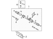
2005 Toyota Solara Steering Gear
Part Number: 44250-AA011$653.07 MSRP: $957.08You Save: $304.01 (32%)Ships in 1-3 Business DaysProduct Specifications- Other Name: Gear Assembly, Power Steering; Rack and Pinion Assembly; Steering Gearbox; Gear Assembly; Gear Assembly, Power Steering(For Rack & Pinion)
- Replaces: 44250-AA010
- Part Name Code: 44250
- Item Weight: 22.00 Pounds
- Item Dimensions: 41.0 x 13.5 x 7.2 inches
- Condition: New
- Fitment Type: Direct Replacement
- SKU: 44250-AA011
- Warranty: This genuine part is guaranteed by Toyota's factory warranty.
2005 Toyota Solara Rack And Pinion
Looking for affordable OEM 2005 Toyota Solara Rack And Pinion? Explore our comprehensive catalogue of genuine 2005 Toyota Solara Rack And Pinion. All our parts are covered by the manufacturer's warranty. Plus, our straightforward return policy and speedy delivery service ensure an unparalleled shopping experience. We look forward to your visit!
2005 Toyota Solara Rack And Pinion Parts Q&A
- Q: How to overhaul the rack and pinion power steering gear assembly on 2005 Toyota Solara?A: The first step for renovating the rack and pinion power rack and pinion assembly requires directing front wheels to a direct forward position. Bolt A should be loosened to remove the clamp from hole cover No.1 and separate hole cover No.2. After fixing the steering wheel with a seat belt to maintain static position, remove the clamp from hole cover No.1 through adjusting bolt A. The steering intermediate shaft assembly needs to be marked together with the power rack and pinion assembly before removing bolt B for their separation. The front wheel must be removed before performing the separation of tie rod assemblies using Special Service Tool: 09628-62011 for both the LH and RH sides. Proceed by detaching the upper side from front stabilizer link assemblies LH and RH. Unbolt the two stabilizer bracket No.1 LH fasteners until you can remove and repeat this process for the RH side. Use Special Service Tool: 09023-12701 dedicated for pressure feed tube assembly disconnection for all vehicles that use 2AZ-FE or 3MZ-FE engines and remove constraining nuts and clamps. For engine type 3MZ-FE remove the power steering rack housing heat insulator before you take out the power rack and pinion assembly through its two bolts and nuts. Secure the power rack and pinion assembly with Special Service Tool: 09612-00012 by wrapping it with tape to prevent damage after disconnecting both left and right turn pressure tubes using Special Service Tool: 09023-38201. You should mark the tie rod assemblies LH and RH before removing them and separate the steering rack boot clips and clamps without breaking the boots. You need Special Service Tool: 09922-10010 to unstake the claw washer and remove the steering rack end sub-assembly after taking out steering rack boots No.2 and No.1. The rack guide removal begins with the spring cap lock nut and rack guide spring cap removal using Special Service Tool: 09631-10021. After this, both the compression spring and rack guide need to be taken off. The power steering control valve removal procedure begins with using a socket wrench (27 mm) to unscrew the rack housing cap. Afterward, install Special Service Tool: 09616-00011 to hold the control valve shaft while you slowly remove the valve and its components and avoid harming the spacer grooves. The upper oil seal of the control valve needs Special Service Tool: 09950-70010 (09951-07150) and a press to remove it before extracting the cylinder end stopper and power rack and pinion. The power rack and pinion bush and oil seal can be removed using service tools 09527-21011, 09612-24014 (09613-22011) for inspection of the power rack and pinion components for runout and wear condition before replacement. Set up the power piston and cylinder tube with fresh oil seals while adequately using lubricant and maintaining correct positioning. Tests of tie rod assemblies LH and RH require assessment for correct torque specifications so replacement occurs when they fail to meet standards. The last installation step involves fitting the power rack and pinion while properly positioning the bush and cylinder end stopper. Secure all components with the correct alignment.
Related 2005 Toyota Solara Parts
 2005 Toyota Solara Power Steering Pump
 2005 Toyota Solara Steering Wheel
 2005 Toyota Solara Drag Link
 2005 Toyota Solara Power Steering Control Valve
 2005 Toyota Solara Power Steering Hose
 2005 Toyota Solara Power Steering Reservoir
 2005 Toyota Solara Rack and Pinion Boot
 2005 Toyota Solara Steering Column
 2005 Toyota Solara Steering Column Cover
 2005 Toyota Solara Steering Gear Box
 2005 Toyota Solara Steering Shaft
 2005 Toyota Solara Tie Rod End