×
ToyotaParts- Hello
- Login or Register
- Quick Links
- Live Chat
- Track Order
- Parts Availability
- RMA
- Help Center
- Contact Us
- Shop for
- Toyota Parts
- Scion Parts
My Garage
My Account
Cart
OEM 2006 Toyota Solara Rack And Pinion
Steering Rack And Pinion- Select Vehicle by Model
- Select Vehicle by VIN
Select Vehicle by Model
orMake
Model
Year
Select Vehicle by VIN
For the most accurate results, select vehicle by your VIN (Vehicle Identification Number).
1 Rack And Pinion found

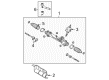
2006 Toyota Solara Steering Gear
Part Number: 44250-AA011$653.07 MSRP: $957.08You Save: $304.01 (32%)Ships in 1-3 Business DaysProduct Specifications- Other Name: Gear Assembly, Power Steering; Rack and Pinion Assembly; Steering Gearbox; Gear Assembly; Gear Assembly, Power Steering(For Rack & Pinion)
- Replaces: 44250-AA010
- Part Name Code: 44250
- Item Weight: 22.00 Pounds
- Item Dimensions: 41.0 x 13.5 x 7.2 inches
- Condition: New
- Fitment Type: Direct Replacement
- SKU: 44250-AA011
- Warranty: This genuine part is guaranteed by Toyota's factory warranty.
2006 Toyota Solara Rack And Pinion
Looking for affordable OEM 2006 Toyota Solara Rack And Pinion? Explore our comprehensive catalogue of genuine 2006 Toyota Solara Rack And Pinion. All our parts are covered by the manufacturer's warranty. Plus, our straightforward return policy and speedy delivery service ensure an unparalleled shopping experience. We look forward to your visit!
2006 Toyota Solara Rack And Pinion Parts Q&A
- Q: How to Service and Repair Rack and Pinion Power Steering on 2006 Toyota Solara?A: The first step for servicing the rack and pinion power steering rack and pinion involves removing the power steering control valve upper oil seal followed by coating the control valve upper bearing with grease and the new oil seal lip with power steering fluid. After that, install the new oil seal using Special Service Tool: 09950-70010 (09951-07150), 09950-60010 (09951-00180, 09952-06010, 09951-00320) and a press tool. Verify proper orientation of the oil seal before moving forward. Install the control valve upper bearing through the utilization of Special Service Tool: 09950-70010 (09951-07150), 09950-60010 (09951-00180, 09952-06010, 09951-00340) and press. New valve spacers need expansion before receiving a power steering fluid coating that allows their proper installation onto the control valve while necessary adjustments should be made. Use Special Service Tool: 09631-20081 by sliding its tapered end over the valve spacers followed by control valve insertion into the valve housing. Ensure the valve spacers and oil seal lip remain intact while you may choose to protect the oil seal by wrapping vinyl tape around the serrated control valve. The new oil seal lip requires power steering fluid coating before you install it correctly using Special Service Tool: 09612-22011 and a press while maintaining the proper orientation. Install two bolts onto the rack housing to secure the control valve housing with a new gasket and correct torque to 20 Nm (204 kgf-cm, 15 ft. lbs.). First grease the needle roller bearing of the rack housing along with the serrated part of the control valve. Use Special Service Tool: 09616-00011 to stabilize the control valve during new lock nut installation at 25 Nm (250 kgf-cm, 18 ft. lbs.) torque. Then apply sealant (Part No. 08833-00080, Three Bond 1344, Loctite 242 or equivalent) to 2 or 3 rack housing cap threads before screwing it with a 27 mm socket wrench to 59 Nm (597 kgf-cm, 43 ft. lbs.). Complete the installation by hammering and punching the cap and housing. Start by greasing the rack guide surface then install it together with the compression spring followed by application of sealant to the spring cap threads before making a temporary installation. You should adjust the total preload by installing RH and LH rack end components temporarily to safeguard the oil seal after which you should torque the rack guide spring cap to 25 Nm (250 kgf-cm, 18 ft. lbs.) using Special Service Tool: 09631-10021 then loosen it so you can turn the control valve to both sides while loosening the spring cap until the compression spring reaches its functional end point. Tighten the rack guide spring cap until the measured preload sits between 1.2 to 1.5 Nm (12.2 to 15.3 kgf-cm, 10.6 to 13.3 ft. lbs.). After applying sealant to the lock nut threads install it temporarily at 51 Nm (520 kgf-cm, 38 ft. lbs.) while using Special Service Tool: 09616-00011 and 09922-10010 by holding the spring cap with a torque wrench that has a 345 mm (13.58 inch) fulcrum length. Recheck the preload measurement before applying MP grease around the control valve shaft and afterward wrapping vinyl tape around the control valve spline before installing the dust cover. Install two new claw washers on the steering rack end sub-assembly before temporarily attaching the LH and RH sub-assemblies with the claws pointed towards the grooves of the rack. Then use Special Service Tool: 09922-10010 to install the rack ends by torquing them to 60 Nm (615 kgf-cm, 45 ft. lbs.) while protecting the rack from impact. Use silicon grease to coat the small opening of steering rack boot No.2 before inserting it into the rack housing groove without causing any damage then follow this procedure on steering rack boot No.1 before proceeding with clamp installation. Use Special Service Tool: 09521-24010 to tighten the rack boot No.2 clamp while achieving a 3.0 mm (0.118 inch) or less clearance, then repeat this procedure for rack boot No.1. The assembly of the two boot clips is completed using pliers before installing the lock nut and tie rod assembly LH to its rack end by matching the marks. Repeated for the RH assembly. Install the left turn pressure tube by applying power steering fluid to two new O-rings before attaching them using Special Service Tool: 09023-38201, torque at 11 Nm (113 kgf-cm, 8 ft. lbs.) using a torque wrench with 250 mm (9.84 inch) fore end. Do the same for the right turn pressure tube. Add the power steering rack and pinion assembly through two bolts and nuts while torqueing them to 70 Nm (714 kgf-cm, 52 ft. lbs.) and follow by installing the power steering rack housing heat insulator. After using Special Service Tool 09023-12701 to connect the pressure feed tube assembly the technician must torques it to 22 Nm (227 kgf-cm, 16 ft. lbs.) at 300 mm (11.81 inch) fulcrum length then repeat the same process for return tube assembly. 2AZ-FE owners should install the tube clamp with nut tightening to 9.8 Nm (100 kgf-cm, 87 inch lbs.) and 31VIZ-FE users need to install both tube clamp and heat insulator with the nut to the torque value of 9.8 Nm (100 kgf-cm, 87 inch lbs.). Farm the front stabilizer bracket No.1 LH by using two bolts which should obtain 19 Nm (194 kgf-cm, 14 ft. lbs.) torque. Perform the same installation process for the RH bracket. Front stabilizer link assemblies LH and RH should be installed first followed by tie rod assemblies LH and RH. Finally, install the front wheel, torquing to 103 Nm (1,050 kgf-cm, 76 ft. lbs.), align the matchmarks on the steering intermediate shaft assembly and power steering rack and pinion assembly, install the bolt and tighten it to 35 Nm (360 kgf-cm, 26 ft. lbs.), install the hole cover No.2 to hole cover No.1, and secure the clamp to hole cover No.1 with bolt A. Bleed the power steering fluid, check for leaks, inspect and adjust the front wheel alignment, ensure the steering wheel center point is correct, and perform steering angle sensor zero point calibration.
Related 2006 Toyota Solara Parts
 2006 Toyota Solara Power Steering Pump
 2006 Toyota Solara Steering Wheel
 2006 Toyota Solara Drag Link
 2006 Toyota Solara Power Steering Control Valve
 2006 Toyota Solara Power Steering Hose
 2006 Toyota Solara Power Steering Reservoir
 2006 Toyota Solara Rack and Pinion Boot
 2006 Toyota Solara Steering Column
 2006 Toyota Solara Steering Column Cover
 2006 Toyota Solara Steering Gear Box
 2006 Toyota Solara Steering Shaft
 2006 Toyota Solara Tie Rod End