×
ToyotaParts- Hello
- Login or Register
- Quick Links
- Live Chat
- Track Order
- Parts Availability
- RMA
- Help Center
- Contact Us
- Shop for
- Toyota Parts
- Scion Parts
My Garage
My Account
Cart
OEM 2005 Scion xA Timing Chain
Engine Timing Chain- Select Vehicle by Model
- Select Vehicle by VIN
Select Vehicle by Model
orMake
Model
Year
Select Vehicle by VIN
For the most accurate results, select vehicle by your VIN (Vehicle Identification Number).
1 Timing Chain found

2005 Scion xA Timing Chain
Part Number: 13506-21050$209.11 MSRP: $298.55You Save: $89.44 (30%)Ships in 1-3 Business DaysProduct Specifications- Other Name: Chain Sub-Assembly, Timing; Chain Sub-Assembly
- Part Name Code: 13506
- Item Weight: 1.20 Pounds
- Item Dimensions: 6.3 x 3.3 x 1.2 inches
- Condition: New
- Fitment Type: Direct Replacement
- SKU: 13506-21050
- Warranty: This genuine part is guaranteed by Toyota's factory warranty.
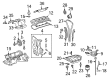
2005 Scion xA Timing Chain
Looking for affordable OEM 2005 Scion xA Timing Chain? Explore our comprehensive catalogue of genuine 2005 Scion xA Timing Chain. All our parts are covered by the manufacturer's warranty. Plus, our straightforward return policy and speedy delivery service ensure an unparalleled shopping experience. We look forward to your visit!
2005 Scion xA Timing Chain Parts Q&A
- Q: How to replace the timing chain on 2005 Scion xA?A: In order to change the timing chain, take out the front wheel, the cylinder head cover, ignition coil, and the ventilation hoses. Empty the engine oil and coolants and take out the water pump assembly. Install timing marks, align crankshaft to TDC and remove crankshaft damper. Install the components in reverse order, with the correct torque requirements. Check oil and coolant leakages.
Related 2005 Scion xA Parts
 2005 Scion xA Cam Gear
 2005 Scion xA Camshaft
 2005 Scion xA Crankshaft Seal
 2005 Scion xA Crankshaft Thrust Washer Set
 2005 Scion xA Cylinder Head
 2005 Scion xA Cylinder Head Gasket
 2005 Scion xA Dipstick Tube
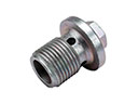 2005 Scion xA Drain Plug
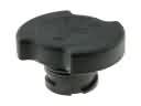 2005 Scion xA Oil Filler Cap
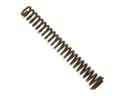 2005 Scion xA Oil Pump Spring
 2005 Scion xA Valve Cover Gasket
 2005 Scion xA Valve Stem Seal