×
ToyotaParts- Hello
- Login or Register
- Quick Links
- Live Chat
- Track Order
- Parts Availability
- RMA
- Help Center
- Contact Us
- Shop for
- Toyota Parts
- Scion Parts
My Garage
My Account
Cart
OEM 2004 Scion xA Timing Chain
Engine Timing Chain- Select Vehicle by Model
- Select Vehicle by VIN
Select Vehicle by Model
orMake
Model
Year
Select Vehicle by VIN
For the most accurate results, select vehicle by your VIN (Vehicle Identification Number).
1 Timing Chain found

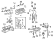
2004 Scion xA Timing Chain
Part Number: 13506-21050$209.11 MSRP: $298.55You Save: $89.44 (30%)Ships in 1-3 Business DaysProduct Specifications- Other Name: Chain Sub-Assembly, Timing; Chain Sub-Assembly
- Part Name Code: 13506
- Item Weight: 1.20 Pounds
- Item Dimensions: 6.3 x 3.3 x 1.2 inches
- Condition: New
- Fitment Type: Direct Replacement
- SKU: 13506-21050
- Warranty: This genuine part is guaranteed by Toyota's factory warranty.
2004 Scion xA Timing Chain
Looking for affordable OEM 2004 Scion xA Timing Chain? Explore our comprehensive catalogue of genuine 2004 Scion xA Timing Chain. All our parts are covered by the manufacturer's warranty. Plus, our straightforward return policy and speedy delivery service ensure an unparalleled shopping experience. We look forward to your visit!
2004 Scion xA Timing Chain Parts Q&A
- Q: How to replace the timing chain on 2004 Scion xA?A: The timing chain replacement process starts with removing the front wheel RH and then proceeding to uninstall the cylinder head cover No.2 by removing its 4 nuts. Commence by unscrewing four bolts that secure the ignition coil No.1 and draw forth the attached four ignition coils. Start by disconnecting both ventilation hoses then proceed to remove the cylinder head cover sub-assembly by uninstalling 9 bolts in addition to 2 nuts. Start by removing the fan together with the generator V-belt and generator assembly and engine under cover RH from the system. Eliminate engine fluid before proceeding to take out the vane pump V-belt along with the water pump pulley and water pump assembly. To access the crankshaft damper sub-assembly set the No.1 cylinder to TDC/compression and match the timing notch with timing mark "0" of the chain cover while keeping the camshaft timing sprocket and gear facing up; if alignment is off adjust the crankshaft 360 degrees so they match. The pulley bolt requires removal with Special Service Tool: 09213-58012 (91111-50845), 09330-00021, while Special Service Tool: 09950-50013 (09951-05010, 09952-05010, 09953-05020, 09954-05021) assists in taking out the damper. Remove the bolt and oil control valve as well as O-ring from the oil control valve connector. Beginning by placing a wooden block under the engine on a jack you should remove the liquid tube bolt holding the insulator before taking out five bolts and the nut. To proceed with the replacement start by unfastening 4 bolts from the engine mounting bracket RH and then unfasten the oil pump assembly along with its accompanying oil pump seal. Avoid crankshaft rotation when chain tensioner assembly No.1 is removed before pushing the plunger while raising the stopper plate upward then holding this plate with a 2.5 mm (0.098 inch) diameter bar. To remove the configuration begin by extracting the chain tensioner slipper and chain vibration damper No.1 from their positions before taking off the chain sub-assembly. To install the components set the crankshaft at ATDC 40 to 140 degrees first then set the intake and exhaust timing sprockets at ATDC 20 degrees before resetting the crankshaft to ATDC 20 degrees. Fasten the chain vibration damper with two bolts which require 9.0 Nm torque before aligning the sprocket matchmarks of the camshaft timing gear with the camshaft timing sprocket and crankshaft timing sprocket. Next, install the chain tensioner slipper (Torque: 9.0 Nm) followed by the chain tensioner (Torque: 9.0 Nm) and finally remove the holding bar from the chain tensioner to check the tension between the exhaust and intake camshaft timing sprockets. Begin installation with the oil pump seal by using Special Service Tool: 09950-60010 (09951-00250, 09951-00380, 09952-06010) combined with 09950-70010 (09951-07100) then install the oil pump assembly and water pump assembly. The procedure involves mounting the RH engine bracket with four bolts at 55 Nm torque strength while adding the RH insulator bracket through five bolts and one nut (A: 45 Nm, B: 52 Nm and C: 52 Nm) followed by liquid tube bolt attachment at 9.8 Nm torque value. Place the camshaft timing oil control valve assembly along with a new O-ring (Torque: 7.5 Nm), afterward install the crankshaft position sensor and water pump pulley through Special Service Tool: 09960-10010 (09962-01000, 09963-00600). The crankshaft damper sub-assembly requires installation with proper alignment of the pin hole toward its designated position while using a pulley bolt that reaches 128 Nm torque. Obtain seal packing (Part No 08826-00080 or equivalent) to apply on the cylinder head cover sub-assembly followed by installation of 9 bolts, 2 seal washers, and 2 nuts (Torque: 10 Nm), later install ignition coil No.1 (Torque: 9.0 Nm) and cylinder head cover No.2 (Nut A: 7.0 Nm, Bolt B: 7.0 Nm). End the process by putting back the generator assembly followed by vane pump V-belt and fan and generator V-belt. At this stage adjust the vane pump V-belt while checking the drive belt deflection and tension. The procedure ends with installing the new gasket on the oil pan drain plug (Torque: 38 Nm) while adding engine oil before leak inspection and engine coolant addition and leak inspection.
Related 2004 Scion xA Parts
 2004 Scion xA Cam Gear
 2004 Scion xA Camshaft
 2004 Scion xA Crankshaft Seal
 2004 Scion xA Crankshaft Thrust Washer Set
 2004 Scion xA Cylinder Head
 2004 Scion xA Cylinder Head Gasket
 2004 Scion xA Dipstick Tube
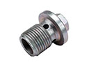 2004 Scion xA Drain Plug
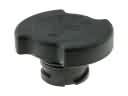 2004 Scion xA Oil Filler Cap
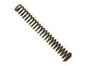 2004 Scion xA Oil Pump Spring
 2004 Scion xA Valve Cover Gasket
 2004 Scion xA Valve Stem Seal