×
ToyotaParts- Hello
- Login or Register
- Quick Links
- Live Chat
- Track Order
- Parts Availability
- RMA
- Help Center
- Contact Us
- Shop for
- Toyota Parts
- Scion Parts
My Garage
My Account
Cart
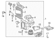
OEM 2005 Scion xA Blower Motor
A/C Heater Blower Motor- Select Vehicle by Model
- Select Vehicle by VIN
Select Vehicle by Model
orMake
Model
Year
Select Vehicle by VIN
For the most accurate results, select vehicle by your VIN (Vehicle Identification Number).
1 Blower Motor found


 Product Specifications
- Other Name: Motor Sub-Assembly, Blower; HVAC Blower Motor Assembly; Blower Assembly; Fan & Motor; Motor Sub-Assembly, Blower W/Fan; HVAC Blower Motor
- Manufacturer Note: COLD SPEC
- Part Name Code: 87103B
- Item Weight: 3.50 Pounds
- Item Dimensions: 9.4 x 9.1 x 10.2 inches
- Condition: New
- Fitment Type: Direct Replacement
- SKU: 87103-52080
- Warranty: This genuine part is guaranteed by Toyota's factory warranty.
2005 Scion xA Blower Motor
Looking for affordable OEM 2005 Scion xA Blower Motor? Explore our comprehensive catalogue of genuine 2005 Scion xA Blower Motor. All our parts are covered by the manufacturer's warranty. Plus, our straightforward return policy and speedy delivery service ensure an unparalleled shopping experience. We look forward to your visit!
2005 Scion xA Blower Motor Parts Q&A
- Q: How to service and repair the blower motor on 2005 Scion xA?A: The first step for blower motor repair includes refrigerant discharge from the refrigeration system through Special Service Tool: 07110-58060 (07117-58080, 07117-58090, 07117-78050, 07117-88060, 07117-88070, 07117-88080). Service Tool 09870-00015 needs to be installed to the piping clamp while ensuring the tube remains free from damage before pressing the tool downward to disengage the clamp lock followed by slow tool extraction while pressing the release lever to drop the piping clamp. The bracket can be separated by removing the bolt which allows users to disconnect the suction hose sub assembly while using vinyl tape for fitting sealing to stop moisture or dirt entry into the system. After removal, users should place the 2 O-rings from the suction hose sub assembly on safe storage. Disconnect the liquid tube sub-assembly A with Special Service Tool: 09870-00025 following the suction hose disconnect procedure. Start by separating the instrument panel sub assembly with passenger Air Bag followed by extracting the lower instrument panel sub assembly with heater duct then taking out the air conditioning amplifier assembly. The ECM removal requires disconnecting the connector, separating the claw clamps, unscrewing two fasteners, repeating the disengaging of the claw clamps to extract the ECM. The air conditioning blower assembly removal requires the user to remove the clamp first followed by connector disconnection then disengaging the 2 clamps and wire harness before removing the 2 bolts and 3 nuts and 2 screws. You should start by disconnecting the wire harness through its 2 clamps and moving on to the air filter case removal by disengaging its 2 claws. After unscrewing the 3 screws of the damper servo sub assembly you must disconnect the blower resistor connector before unscrewing the 2 screws to proceed. The blower motor cover removal requires disconnecting the rod followed by unscrewing and removing the holding spring while taking out the 4 screws from the rod and connector. Use the 2 claws on first to detach Thermistor No.1 and continue by removing packing together with the air conditioning tube assembly using a 5mm hexagon wrench and then extract the 2 O-rings. Use a 4mm hexagon wrench to remove the cooler expansion valve by unbolt its two screws until they release. Afterwards install the cooler evaporator sub assembly No.1 by unscrewing it and disassembling its facets with two claws and then remove the evaporator cover and sub assembly together with two O-rings. Secure the cooler evaporator sub assembly No.1 onto the heater case after applying compressor oil (ND-OIL 8 or equivalent) to the contact surfaces of 2 new O-rings while installing them first and screwing 3 bolts for the evaporator cover followed by screwing a bolt and attaching 2 claws for the air duct. The air conditioning tube assembly needs installation by distributing compressor oil on two new O-rings before torquing it to 5.4 Nm (55 kgf.cm, 48 in.lbf) with a 5mm hexagon wrench. The procedure ends with packing installation. First reattach the lower instrument panel sub assembly with heater duct and install the instrument panel sub assembly with passenger Air Bag assembly. Follow these steps for sub assembly A of liquid tubes: remove vinyl tape, apply compressor oil to two fresh O-rings, place the rings and test the fitting between piping clamp claws. Routine the suction hose sub assembly tasks after completing connection tests of the claw fitting and install the bracket with a 9.8 Nm (100 kgf.cm, 87 in.lbf) bolt torque. The system requires charging with refrigerant via Special Service Tool: 07110-58060 (07117-58060, 07117-58070, 07117-58080, 07117-58090, 07117-78050, 07117-88060, 07117-88070, 07117-88080) to 460 plus or minus 30 g (16.2 plus or minus 1.1 oz.) while warming the engine to check for leaks.
Related 2005 Scion xA Parts
 2005 Scion xA A/C Accumulator
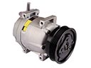 2005 Scion xA A/C Compressor
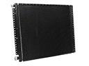 2005 Scion xA A/C Condenser
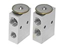 2005 Scion xA A/C Expansion Valve
 2005 Scion xA A/C Hose
 2005 Scion xA A/C Switch
 2005 Scion xA Ambient Temperature Sensor
 2005 Scion xA Blend Door Actuator
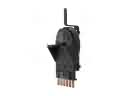 2005 Scion xA Blower Control Switches
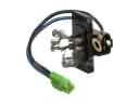 2005 Scion xA Blower Motor Resistor
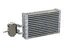 2005 Scion xA Evaporator
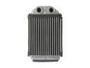 2005 Scion xA Heater Core