×
ToyotaParts- Hello
- Login or Register
- Quick Links
- Live Chat
- Track Order
- Parts Availability
- RMA
- Help Center
- Contact Us
- Shop for
- Toyota Parts
- Scion Parts
My Garage
My Account
Cart
OEM 2004 Toyota Sienna Water Pump
H2O Pump- Select Vehicle by Model
- Select Vehicle by VIN
Select Vehicle by Model
orMake
Model
Year
Select Vehicle by VIN
For the most accurate results, select vehicle by your VIN (Vehicle Identification Number).
1 Water Pump found


2004 Toyota Sienna Water Pump
Part Number: 16100-29085$75.09 MSRP: $105.41You Save: $30.32 (29%)Ships in 1-3 Business DaysProduct Specifications- Other Name: Pump Assembly, Water; Engine Water Pump; Water Pump Assembly; Pump Assembly, Engine Water
- Replaces: 16100-09070
- Part Name Code: 16100
- Item Weight: 2.50 Pounds
- Item Dimensions: 10.0 x 6.5 x 5.9 inches
- Condition: New
- Fitment Type: Direct Replacement
- SKU: 16100-29085
- Warranty: This genuine part is guaranteed by Toyota's factory warranty.
2004 Toyota Sienna Water Pump
Looking for affordable OEM 2004 Toyota Sienna Water Pump? Explore our comprehensive catalogue of genuine 2004 Toyota Sienna Water Pump. All our parts are covered by the manufacturer's warranty. Plus, our straightforward return policy and speedy delivery service ensure an unparalleled shopping experience. We look forward to your visit!
2004 Toyota Sienna Water Pump Parts Q&A
- Q: How to replace the water pump assembly on 2004 Toyota Sienna?A: To replace the water pump assembly, first drain the coolant, then remove the front wheel RH, front wiper arm head cap, front wiper arms RH and LH, cowl top ventilator louver sub-assembly, wiper link assembly, cowl top to cowl brace inner No.1, cowl top panel sub-assembly outer front, front fender apron seal RH, V (cooler compressor to crankshaft pulley) belt No.1, vane pump V belt, engine moving control rod, engine mounting stay No.2 RH, generator bracket No.2, and crankshaft pulley using Special Service Tools: 09213-54015 (91651-60855), 09330-00021, 09950-50013 (09951-05010, 09952-05010, 09953-05020, 09954-05031). The following sequence for removing components includes timing belt No.1 cover, timing belt No.2 cover, engine mounting bracket RH, timing belt guide No.2, timing belt, timing belt idler sub-assembly No.2, and camshaft timing pulley while using Special Service Tools: 09960-10010 (09962-01000, 09963-01000), 09249-63010. You need a 10 mm socket hexagon wrench to remove the pivot bolt of timing belt idler No.1 and plate washer when taking out timing belt idler sub-assembly No.1 and timing belt No.3 cover. The water pump assembly requires removal by unfastening three bolts and three nuts along with the water pump itself. The first step for installation is to insert a new water pump gasket along with the 3 bolts and 3 nuts to attach the water pump. Apply torque of 8.0 Nm (82 kgf-cm, 71 inch lbs.). Then install the timing belt idler sub-assembly No.1 by utilizing a 10 mm socket hexagon wrench to fasten the plate washer to the pivot bolt and timing belt idler No.1 with torques 34 Nm (347 kgf-cm, 25 ft. lbs.). The maintenance process continues with the procedure of installing the timing belt No.3 cover and camshaft timing pulley with Special Service Tools: 09960-10010 (09962-01000, 09963-01000), 09249-63010 and timing belt idler sub-assembly No.2 followed by timing belt inspection then timing belt installation with Special Service Tool: 09960-10010 (09962-01000, 09963-01000). From this point begin installing the chain tensioner assembly No.1 together with timing belt guide No.2 along with engine mounting bracket RH as well as timing belt No.2 cover and timing belt No.1 cover and crankshaft pulley using Special Service Tools 09213-54015 (91651-60855) and 09330-00021. To complete the task you must install the generator bracket No.2 then put the engine mounting stay No.2 RH with the engine moving control rod following installation of the vane pump V belt and V (cooler compressor to crankshaft pulley) belt No.1. Check the drive belt deflection and tension before installing the cowl top panel sub-assembly outer front and cowl top to cowl brace inner No.1. After putting the wiper link assembly and front wiper arms LH and RH add the front wheel RH and conduct tests for engine coolant leaks.
Related 2004 Toyota Sienna Parts
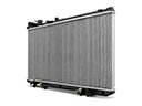 2004 Toyota Sienna Radiator
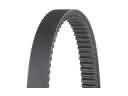 2004 Toyota Sienna Drive Belt
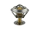 2004 Toyota Sienna Thermostat
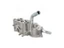 2004 Toyota Sienna Thermostat Housing
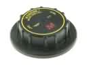 2004 Toyota Sienna Radiator Cap
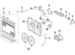
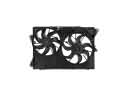 2004 Toyota Sienna Cooling Fan Assembly
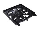 2004 Toyota Sienna Cooling Fan Module
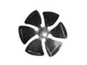 2004 Toyota Sienna Fan Blade
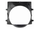 2004 Toyota Sienna Fan Shroud
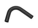 2004 Toyota Sienna Radiator Hose
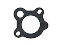 2004 Toyota Sienna Thermostat Gasket
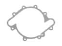 2004 Toyota Sienna Water Pump Gasket